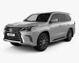
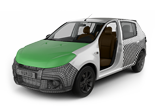
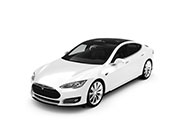
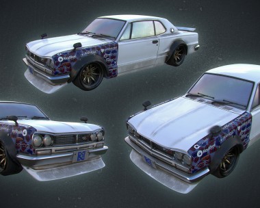
 자동차
자동차
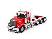 트럭
트럭
 버스
버스
 모터사이클
모터사이클
 군용 차량
군용 차량
 전자 기기
전자 기기
 무기
무기
 건축물
건축물
 항공기
항공기
 가구
가구
 캐릭터
캐릭터
 동물
동물
 우주선
우주선
 음식
음식
 선박
선박
보기
The motivation for this project came from a visit at the Mercedes Benz museum in Stuttgart, Germany where I have been very impressed by seeing the Mercedes 300 SL live for the first time.
The environment for the modelling and visualization project has been set up in Rhinoceros 5 (McNeel). Reference images and blueprints have been collected from the Internet in order to start with a good base. It has been chosen to create the entire 3D model using the Curve modelling technique. Once a good quality blueprint has been found, the views have been arranged with the appropriate blueprint (top, front, back, left, right). In that case the DesktopBackground has been used as the command, but it could also be better done with the PictureFrame command (since Rhino 5).

The single blueprints have to be equally scaled and precisely positioned in space in order to be able to reference each other. A good trick to achieve this is to create a bounding box based on the initial blueprint, which can be used as help for scaling the remaining blueprints to fit. For the scale of the model it is suggested to use the real dimensions (as defined references of construction drawings, blueprints, etc.). Anyhow this is not necessary, as the whole model can be re-scaled at any time of the modelling process.
The next step was to define the guide curves, which would be responsible for constructing the car body surface. Following the blueprint the interpolated curves defined the whole car body in 3D space using the InterpCrv command. Most certainly it was only necessary to model and define one half of the model, as the second half could be mirrored along the center plane. A bounding box around the whole construction space was used as a dummy for midpoint snap and as reference points in space.

At the same time also the doors and the window surfaces have been traced with an interpolated line in 3D space in order to have guides for later cutting the main body surface into separate pieces (light openings, doors, windows,..). Once the main guide curves for the car body surface have been defined, they were transformed into a surface using the Loft command. It was necessary to use the Loft option Loose to generate a relaxed surface.
One of the most tricky parts of the whole modelling process however was a clean definition of the guide curves as the resulting surface, as kinks and unequal control points had to be avoided in the guide curves. Lofting the curves together it is very recommendable to use the same number of control points in the guide curves. In order to achieve that the Rebuild command was used to equally spread and define the number of the control points along the guide curves. If the car body surface is not clean, this will generate many problems in the further modelling steps, as cut out surfaces and other constructions will tightly rely on the main car body surface.

The resulting main car body surface can be mirrored along the middle plane in order to construct the whole car body. It is necessary to check the seam of the joined surfaces as most likely there could be a kink. To get rid of the kink at the seam, the control curve can be readjusted. The next step is to further optimize the main car body surface for a smoother result. For this procedure the Rebuild as the Smooth commands can be used. Once the result is satisfactory to our criteria the doors, windows, front grill, lights, wheels and others can be cut out of the main car body surface. For this procedure I recommend the Split command.

Details as the car body surface bumps (front, side above the wheels) have been modelled using the Sweep command. For those bump surfaces guide curves have been generated and positioned in space. For an exact join with the above surface the outline guide curves can be projected onto the above surface using the Project command. The bump surfaces can also be made larger and be split with the above surface in order to get a clean join of the separate surfaces. In some other cases the BlendSrf command has been used to precisely blend surfaces.

Once the all the openings and cuts have been separated from the main car body surface, the further task was the detailing of the car body as the modelling of the front grill, bumpers, lights, etc..

The details have been modelled based on the blueprints and mostly the reference images. The logo has been written using the Text command and later projected on the main car body surface. Once the logo curves (text) were in right position they were split from the man car body surface and in a second step offset using the OffsetSrf command.

The windshield wipers as their openings have been constructed using curves for cutting outs and blending the surfaces (old, new) together.

The lights have been constructed starting from the border curve of the cut in the main car body surface, that has been defined for the light position. The border of any surface can be created using the DupBorder command. As the lights were symmetrical along their central point it was suitable to create a guide curve, which has been revolved around its center in 360 degrees using the Revolve command.

The grill has been constructed using the border curve of the cut in the main car body surface. From that starting point it has been adjusted to correspond the references. A bit a tricky part has been to model the bumpers as the geometry is very free-form based. Guide curves have been positioned in space and joined together mostly using the sweep method. A very useful command for editing solid objects is the SolidPtOn command in order to manipulate the solids in real-time without having to rebuild them, upon prior manipulating their construction curves.

Additional details as the windshield and door window frames have been constructed using the border curves for an additional step using the Pipe command. Prior to that step the curves have been offset to their interior using the Offset command.

The wheels were modelled by following the blueprint guidelines. Circles were positioned in space and lofted together in a second step in order to achieve the desired form. The logo in the center has been projected on the base surface and constructed the analog ay as the car text logo (cut from base surface and offset surface). For the tires a simple guide curve defined the shape and has been swept along a rail curve. The profile of the tire has been achieved as 3D geometry using the ApplyDisplacement command (new in Rhino 5). This required some testing to achieve the desired result.
For the construction of the car interior it was necessary to understand and filter out the main guide curves, which would be used for the interior surface construction. Most likely this was the trickiest part of the modelling process.

A good starting point was to duplicate the relevant surface edges and start from there. Once the guide curves have been positioned in space different lofting and sweeping techniques have been applied in order to model the interior surface. Firstly separate surfaces have been modeled to be later joined into a whole surface. In this step (similar to the main car body surface adjustments) quite some adjustment as optimization steps were necessary to get a smooth and relaxed surface. The MergeSrf command among others, was used to join the fragmented surfaces into a whole surface for the interior body. Only the dashboard has been left as a separate surface for later texturing purposes.
The seats have been done as separate objects with guide curves and manipulation of their geometry using the CageEdit command. This command has been used throughout the whole modeling process, although care has to be taken, considering that this command generates a denser surface (in terms of the control points body) and obviously deforms the geometry. Nevertheless it is a very useful and sometimes fast solving problem command, considering its imprecise manipulation method. Additional detailing of the seats has been achieved using guide curves and making pipes out of them afterwards.

The dashboard as its instruments have been carefully modelled in analogy to reference images, as the blueprints did not show that interior detail. The process was the same as in previous steps using guide curves with projection, sweeping, lofting and cage editing.

When the interior was finished some small details have been readjusted and the geometry cleaned up for the next steps of texturing and visualization.
As the initial intent it has been chosen to model the Mercedes 300 SL (Gullwing) using the Curve modelling technique. It was an interesting modelling project with lots of control and experience gained. Based on other projects and the definition of the free form geometry of the car, it would be very wise as-well to use the SubD technique, whereby the fine tuning and smoothness adjustment of the main car body surface would be fairly easier and faster. It is previewed that the next version of Rhinoceros (Rhinoceros 6) will have SubD tools implemented according to McNeel. Until then plugins like T-Splines and Clayoo can be used within Rhinoceros to model with SubD tools or the use of other Modelling software would allow SubD modelling as-well.
 Modelling")
 Modelling")
 Modelling")
 Modelling")
 Modelling")


Thanks all for reading. Please leave your comments and feel free to contact me.
Jan Kokol
IMAGO Design
www.imagodesign.at


This making open my eyes! Now i have understain the model workflow with curves on Rhino.
GREAT JOB! your render is perfet. Please let this making of online for all, is very useful!! THANK you!
Thanks Gino. The next car has been done using T-Splines in Rhino. I will post a tutorial of the Porsche 911 in Rhino in the next months.
je suis bluffer ! good job. combien de temps faut il à l’artiste pour réaliser un modèle en général ?