

 Carros
 Caminhões
 Autocarros
 Motociclos
 Militar
 Eletrônicos
 Armas
Armas
 Edifícios
 Aeronaves
 Móveis
 Personagens
 Animais
 Nave Espacial
 Alimentação
 Navios
mais
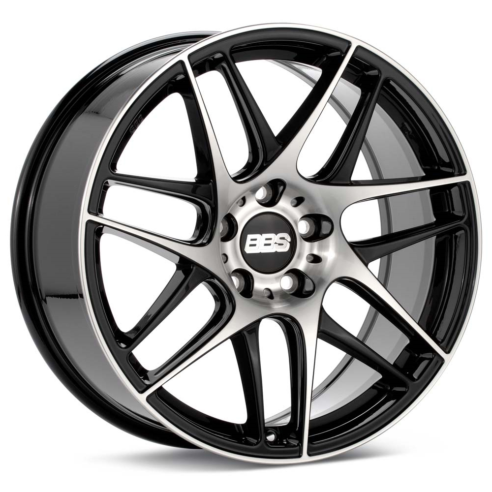
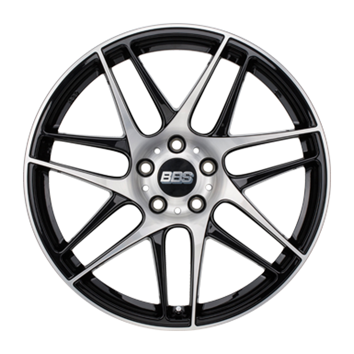
Hi everyone! It is time to make a tutorial of the modeling a car rim in 3ds Max! Such a simple detail and so much influence on the perception of the car. The first thing that tuning studio does with a car is that it sets new superior rims. So we are going to start with superior rims! Recently we have found some suitable rims – BBS CX-R.
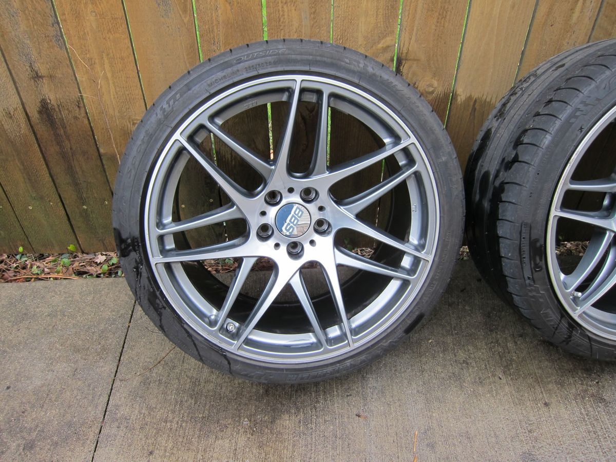
You may ask why these rims? This is simple! They combine the incompatible qualities: on the one hand, they are sports and aggressive and on the other hand, there is no pretentiousness and nothing is superfluous. Neat design, but they have a zest. And the main factor is that they are easy to model for the newcomer even though their zest.
For our task, we need:
– Free time and the desire
– 3ds Max (it can be any other 3D editor, but then you have to look for the features I’m going to use by yourselves)
– Photoshop (It can be any other raster editor, but then you have to look for the features I’m going to use by yourselves)
Actually, we will need Photoshop only if our references are different from the standard view. We have to model from photos, because very often there are no blueprints for necessary rims. And the photos of the desired rim don’t always have the perspective view of the left or the right. In this case, we will have some inaccuracies, which are entirely dependent on our accurate eye.
So there you go!
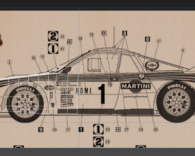
Let’s start with the most unpleasant scenario, when we don’t have photos of the view of the left and the right and blueprints.
Here is a picture, which is very easy to process so that it would be easy to work with it.
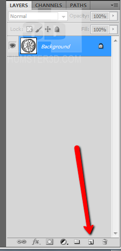
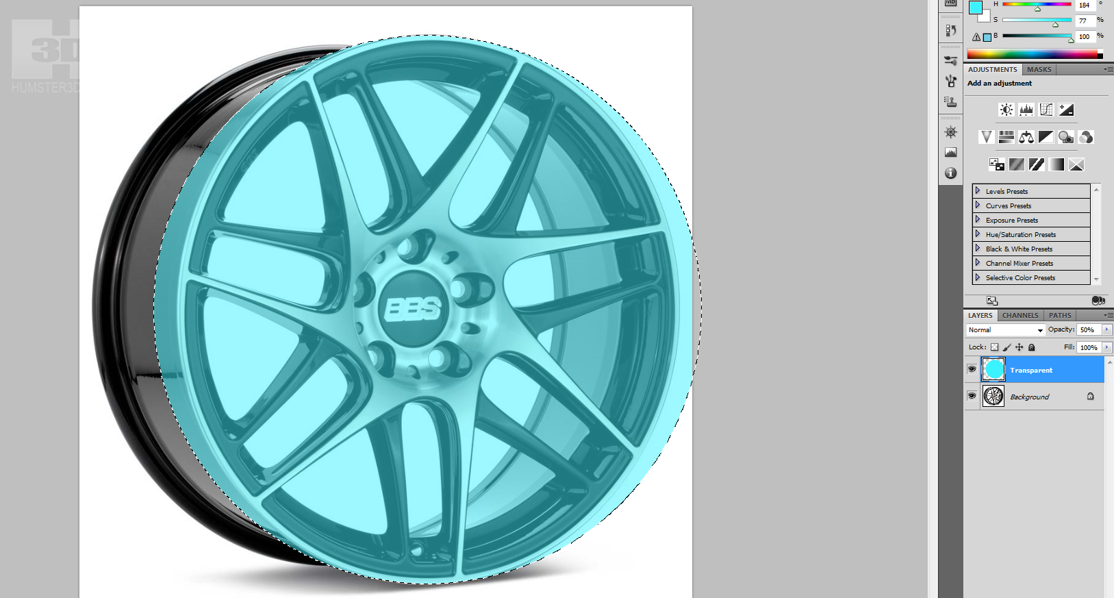
We open Photoshop and begin to cast a spell of the correct perspective. For this, we create a layer over the image and make it 50% transparent. You can do this by pressing this button:
Now set it necessary attributes – the name to simplify understanding and the transparency.
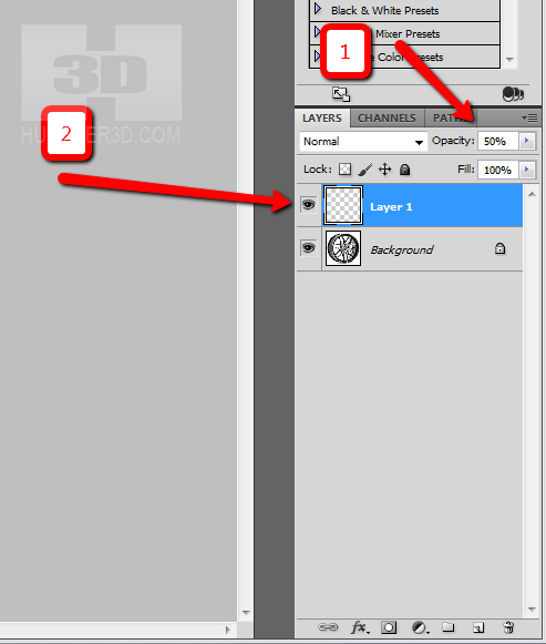
On the mark 1, enter a value of 50%, which is responsible for opacity, then make a double click on the layer and enter the name Transparent.
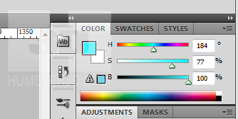
Now set the fill color, which will contrast with the background of the picture.
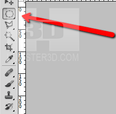
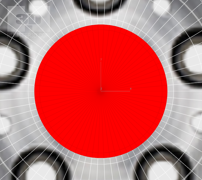
Select ‘Elliptical Marquee Tool’
Press ctrl + alt + shift and begin to select a circle, put the center of the circle in the center of the rim and the border of the circle match with the border of the rim. This is needed to fit the border of the rim under the circle to make it easy to work with it. If you didn’t fall directly into the center of the rim it’s not a problem. In addition to already pressed ctrl + alt + shift press space. Now fill the selected area with the prepared color using combination alt+backspace. Please note you have to select the layer called Transparent. We should have something like this:
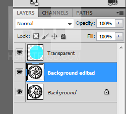
Now duplicate the main layer and name it Background edited, because we won’t be able to edit substrate layer as we need.
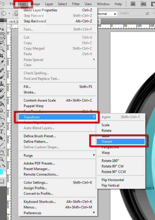
Now you need to select ‘distort’ function.
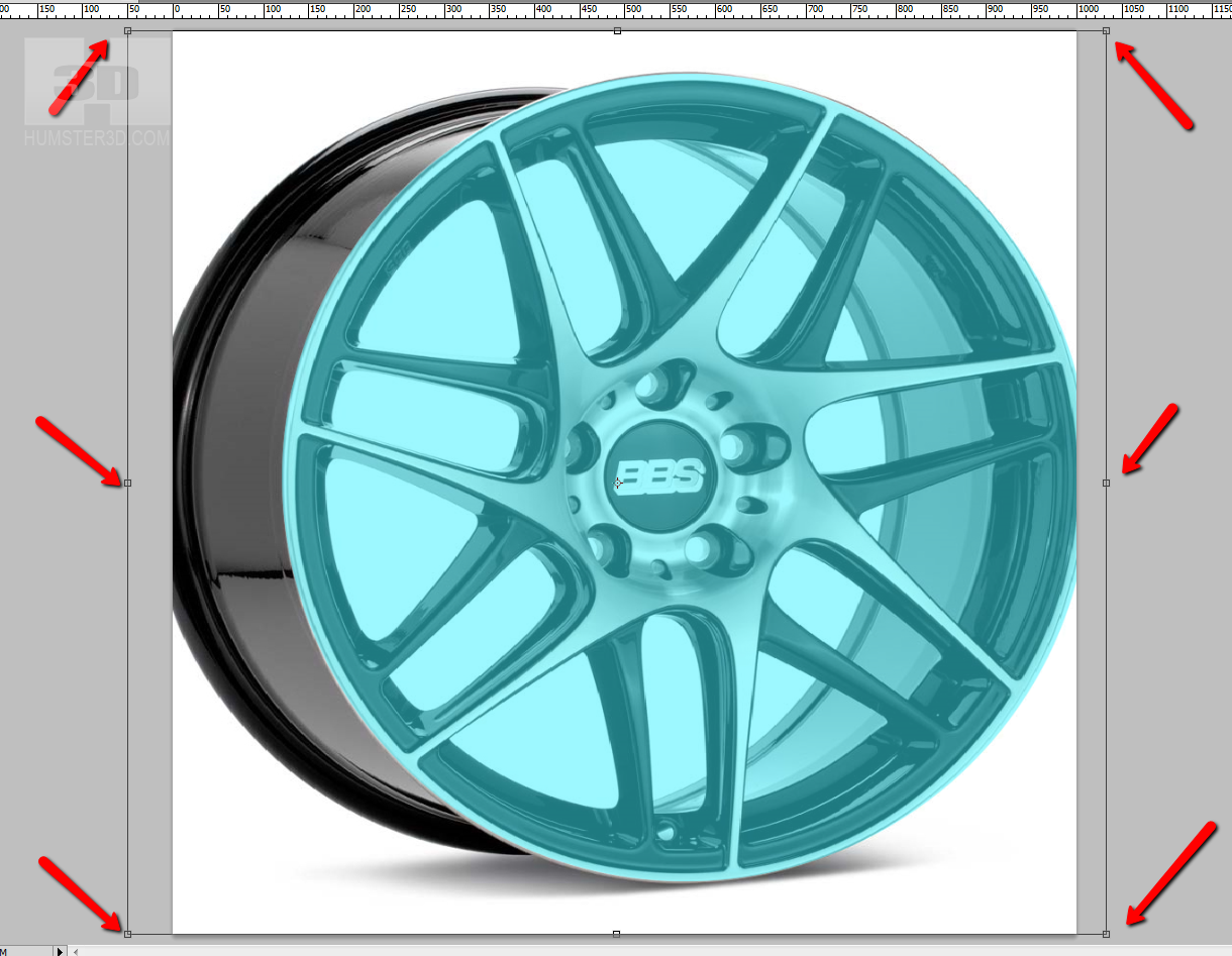
Adjust the control points of our image to the circle, and don’t forget to press Enter to apply the application.
Now disable the layers Transparent and Background and save our ready reference to the convenient place.
Finally the most interesting part. Open 3ds Max. We are going to use more appropriate image for the modeling, which we happen to find on the Internet.
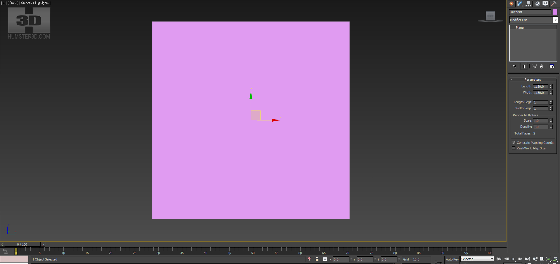
Go to the front view and create a Plane with 0, 0, 0 and the size corresponding to the size of the image in pixels. If you have the 1150х1150 image, you need to create a Plane with the size 1150х1150 units, which is selected by default in 3ds Max. Name it Blueprint.
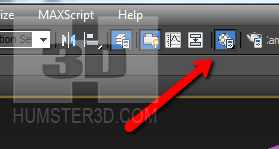
The next step is to open Material Editor. Button on the toolbar or the hotkey M.
Name the material ‘blueprint’ and download there prepared texture.
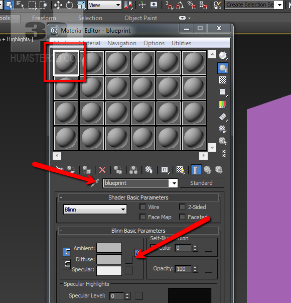
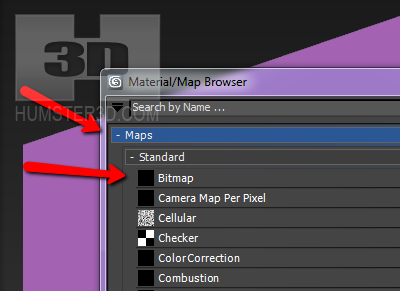
Then open a window of the texture search, we can find it in the prepared place.
Assign the material to our Plane and activate the display of the texture in the viewport.
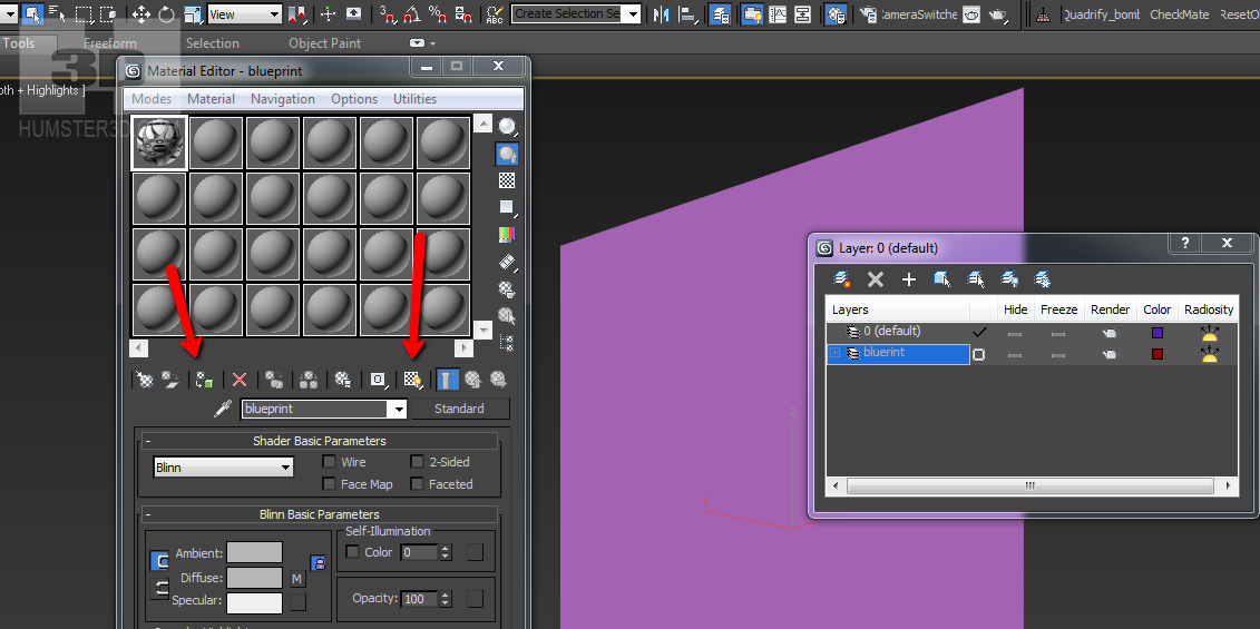
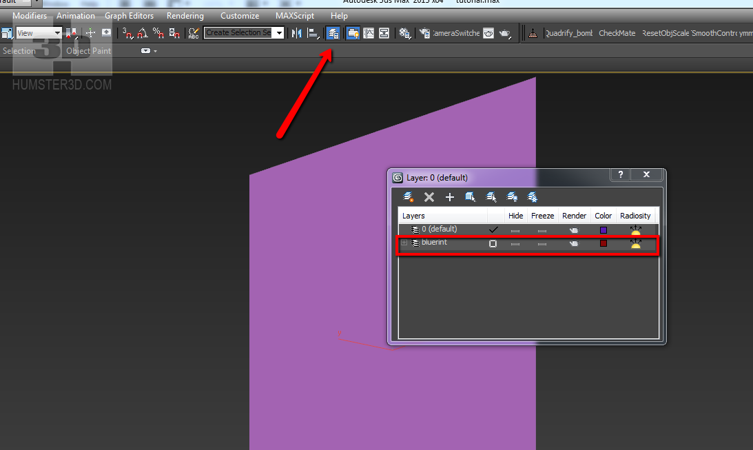
Now move the created Plane to the separate layer.
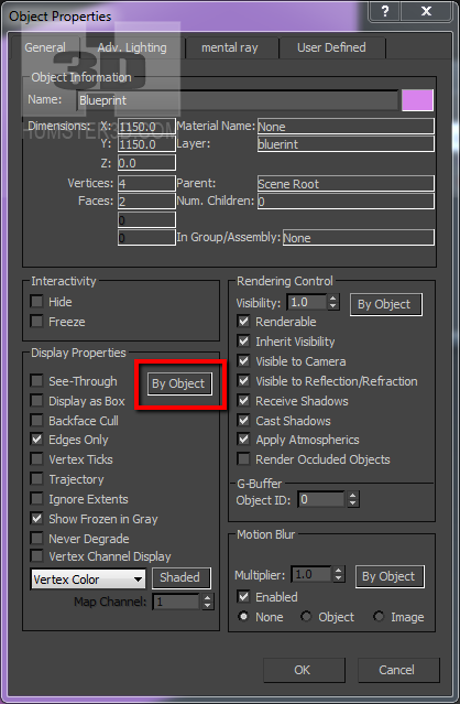
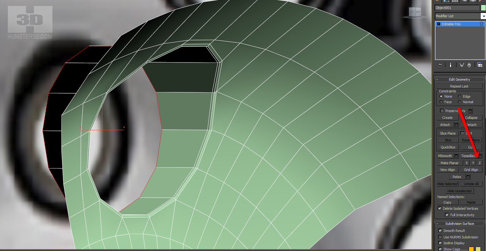
Right click on the current Plane and choose Object Properties.
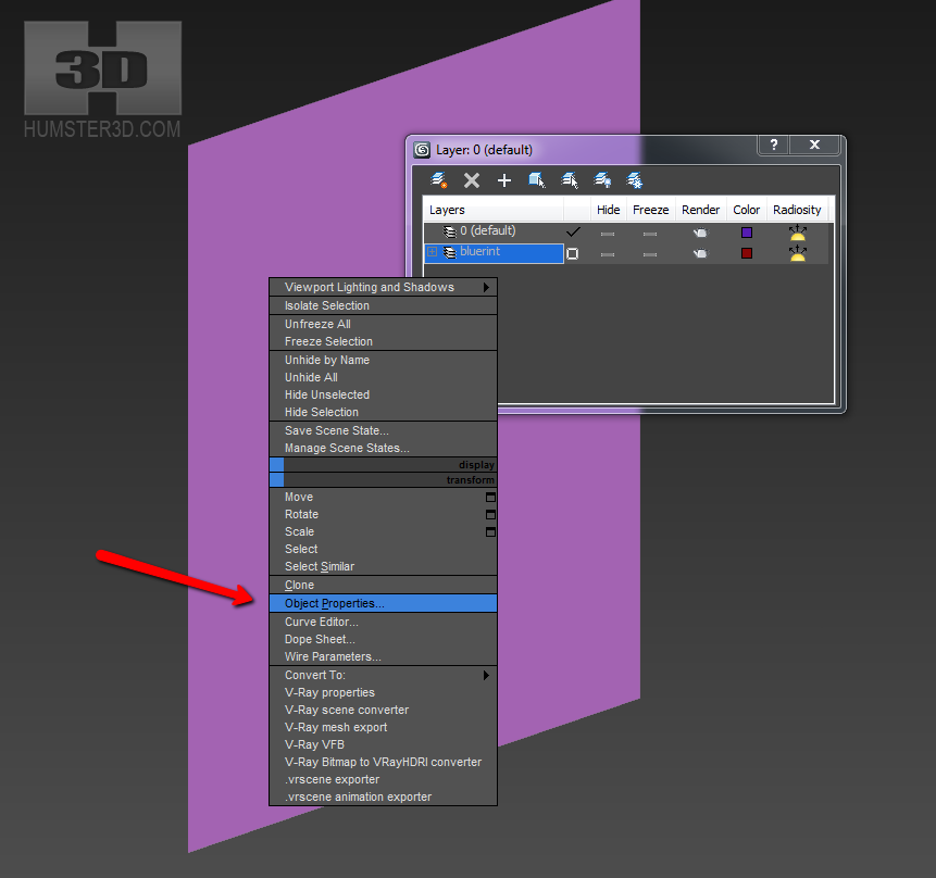
Next, we click only one button in the object properties, which activates a control of the object according to the properties of the layer.
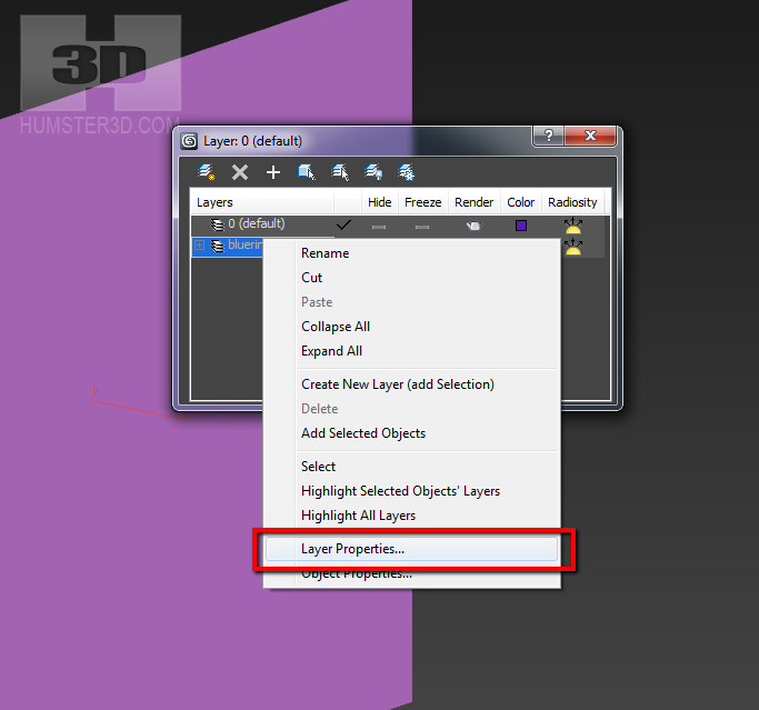
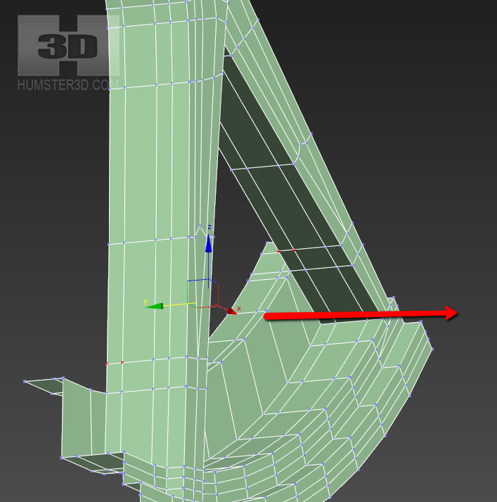
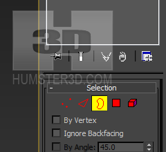
Right click on the ‘Blueprint’ layer and select Layer Properties.
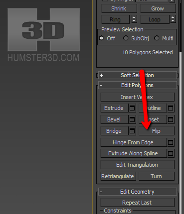
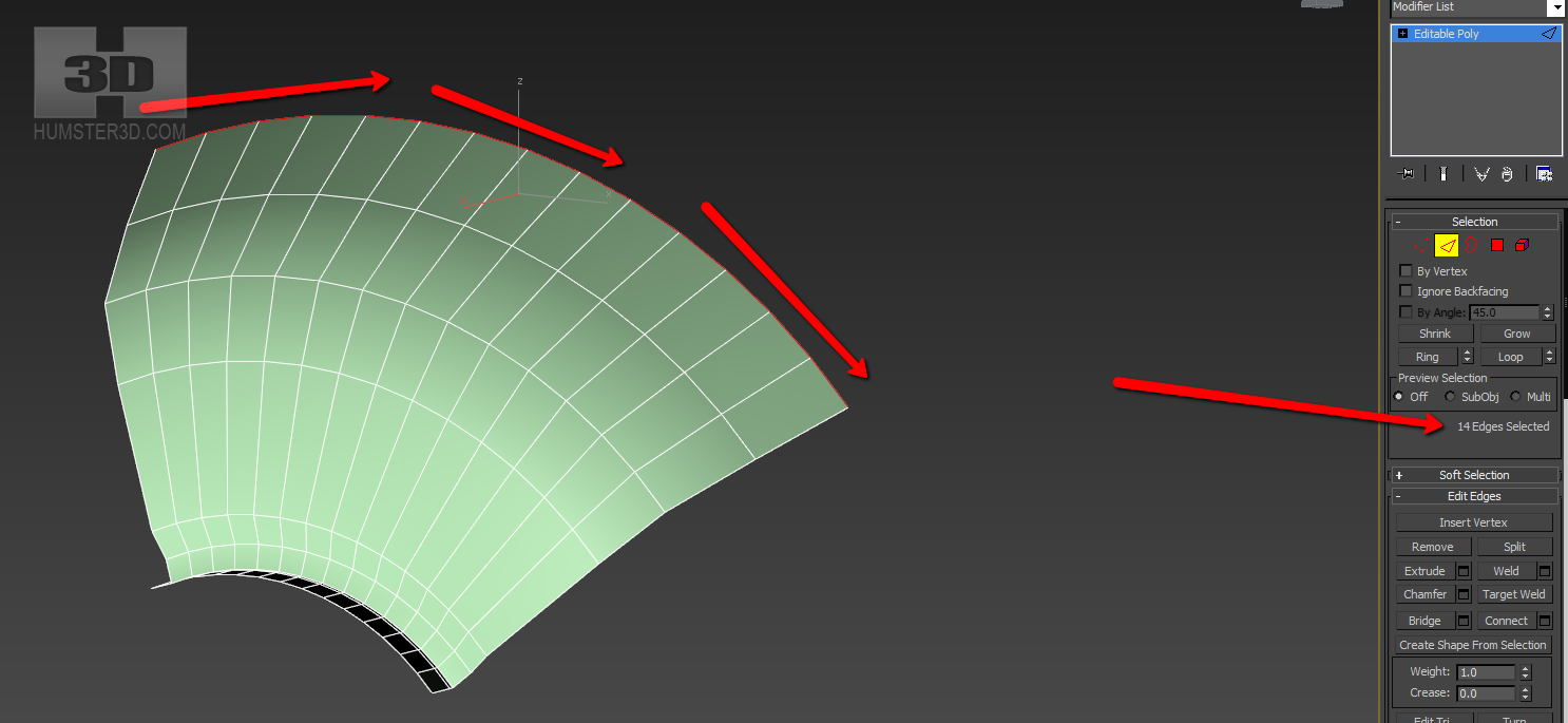
The red arrows show the attributes that you have to include and the blue arrows show the attributes you need to disable, the green rectangle shows that you have to choose Shaded from the drop down list.

All these actions over the layers aren’t necessary, but they significantly simplify your work. Now when you go to Wireframe mode Plane Background will be opaque making the modeling work easier.
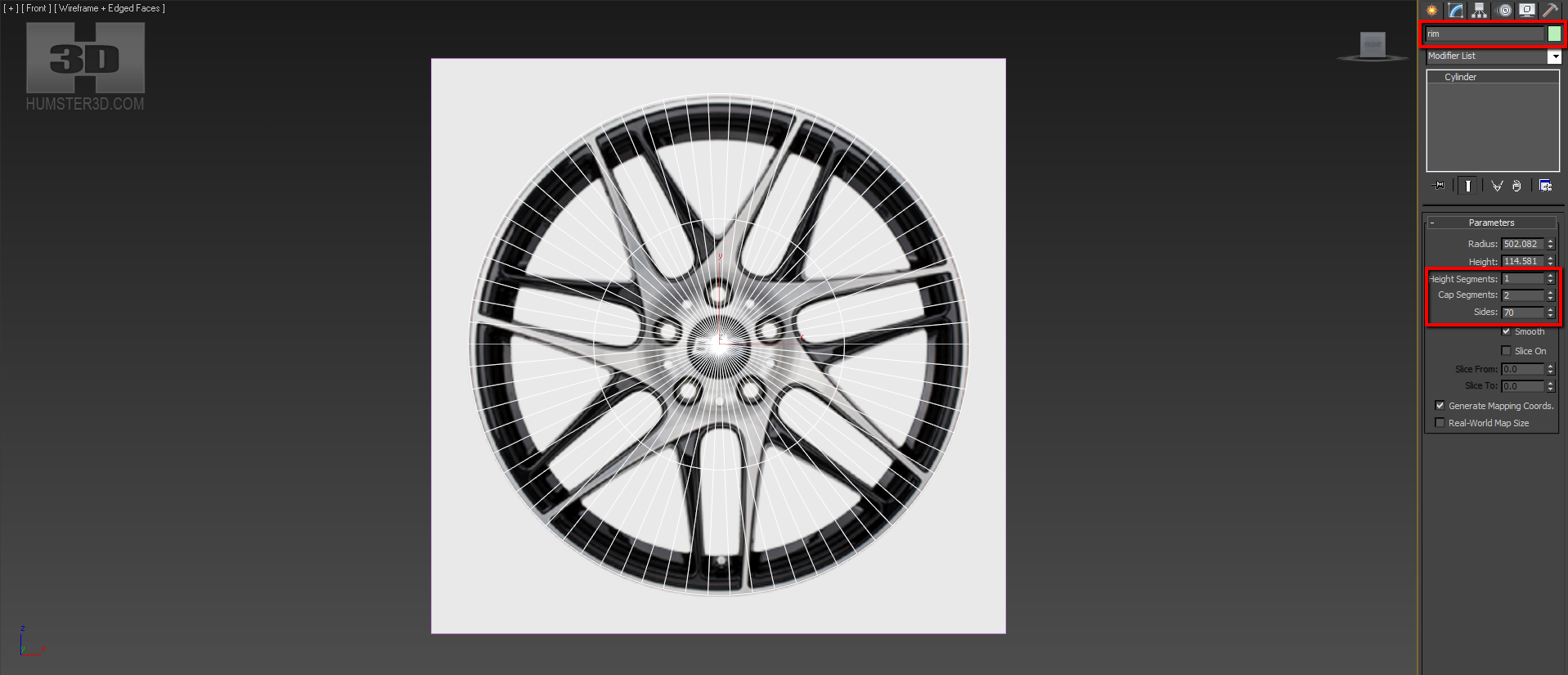
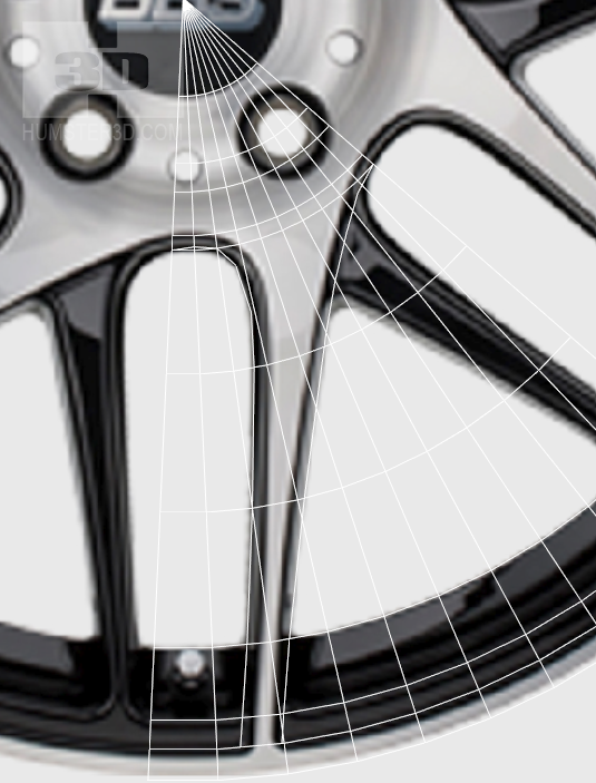
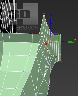
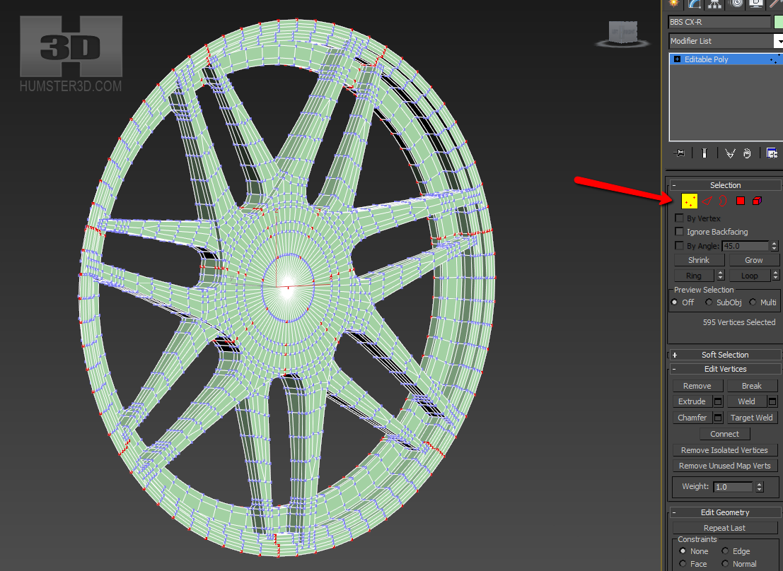
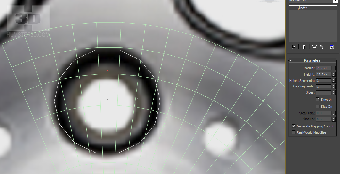
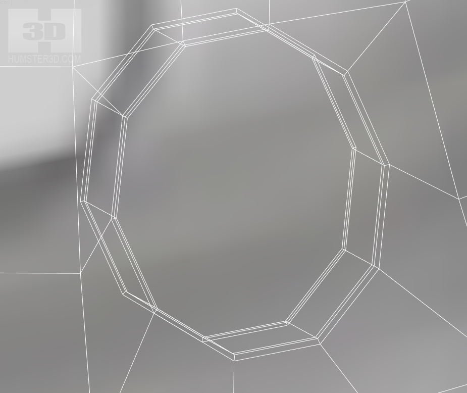
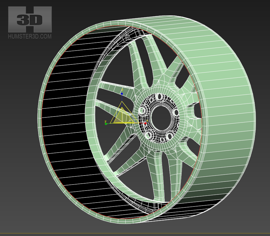
Now a little bit of theory. Since the rim is a rotating body, we will start the modeling with a cylinder. We need to calculate the number of segments to make our rim well converged, as we are going to model only one arm and then just duplicate it. We have two sets of arms, seven arms in each and two pair of nut holes, five pieces in each. To duplicate the arms and nut holes properly the number of segments has to be arithmetical mean between the number of arms and nut holes or to be a multiple of that number. First, we are going to make the front row of arms and for our calculation, we take the number of holes equal to 5. We also have thin arms and in order to minimize the deformation of the rim we need to use more segments. The easiest way to find the arithmetical mean is to multiply the two numbers. 7×5=35, but it’s not enough, so we take a multiple to this number, 70. Immediately set the number of Cap Segments 2 to simplify the work with the blank and do not forget to name our mesh.
Live from our cylinder only the Cap.
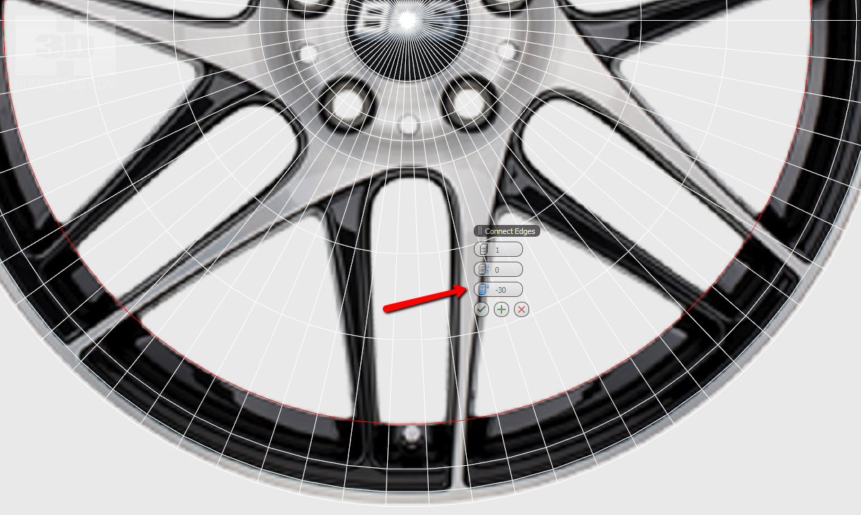
Using Connect, we outline all radial dimensions. We can adjust the radius using this slider. I also suggest outlining 2-3 segments on arms to bend them properly.
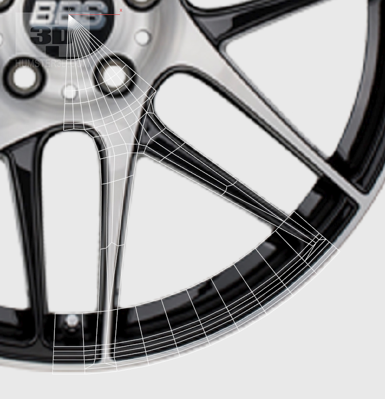
Now leave 10 segments per one arm. We advise you to start with an arm, which is looking at six o’clock, because it is straight and it will be easy to work with it.
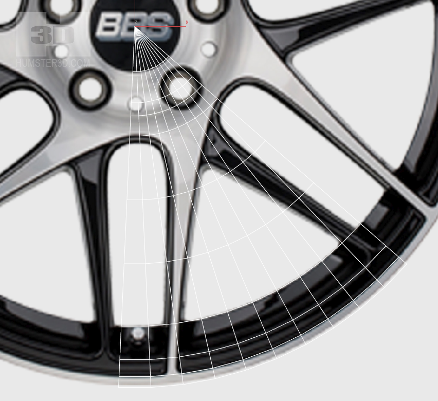
Outline the arm using Cut. It is very important to differ the colored part of the rim from the border of the object.
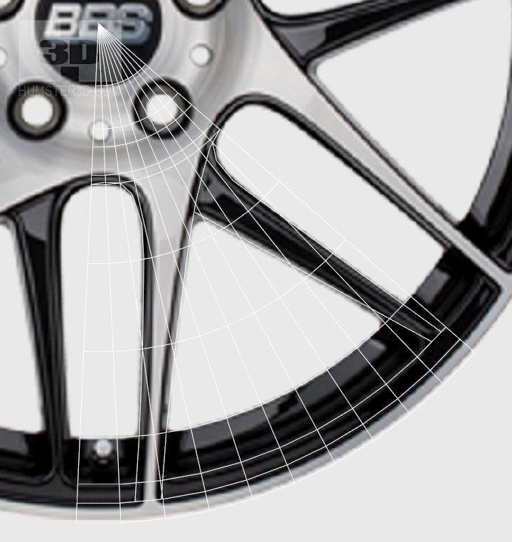
Please never do such mistakes! Here we have specially showed how you shouldn’t do. We need to model the geometry of the rim and not its paint.
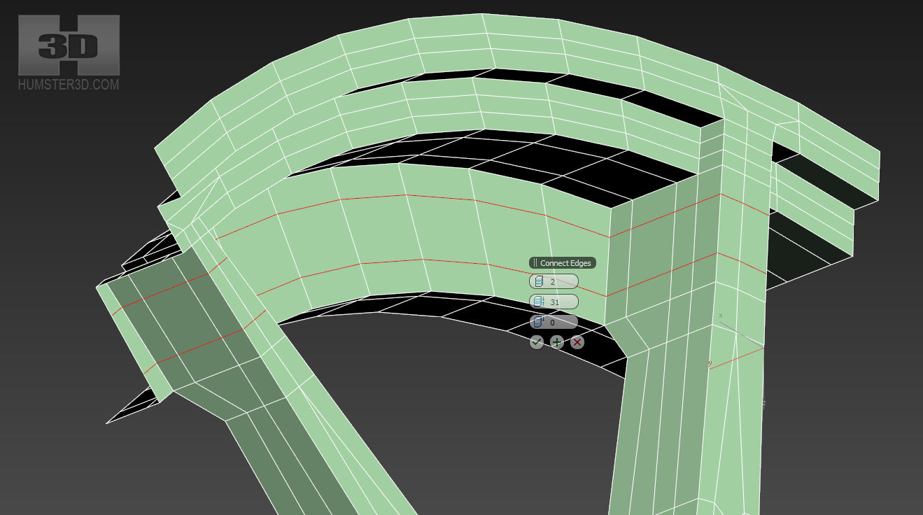
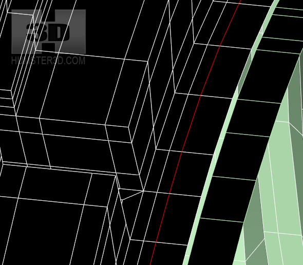
To converge rim well after the duplication you need to draw one more Loop on the border of the material using Connect.
Now just draw out the silhouette of the arm using Cut. Don’t bother about the wrong topology, we will fix it later.
Outline the second arm.
Remove all unnecessary polygons
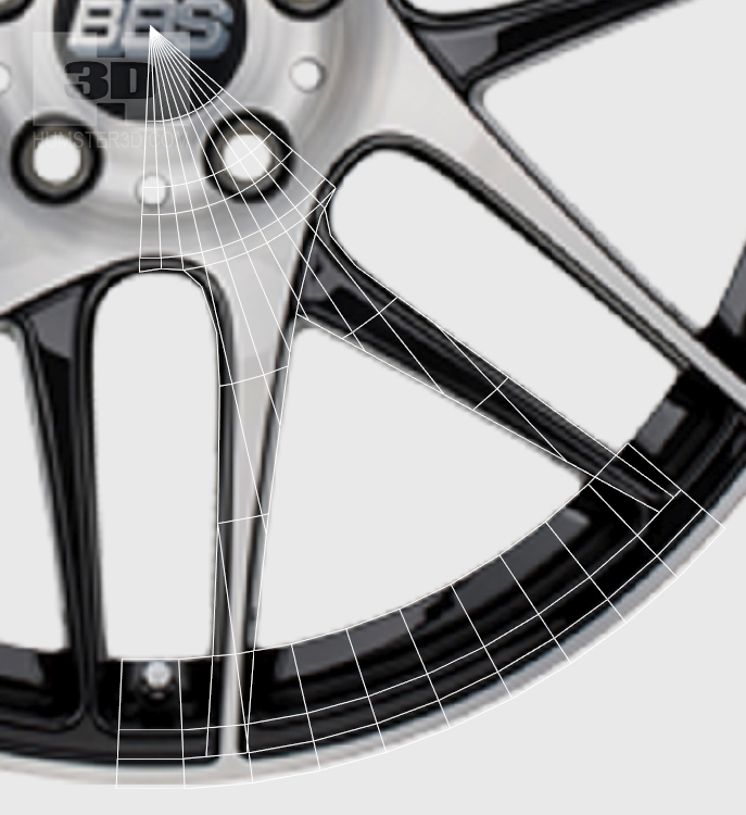
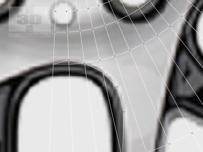
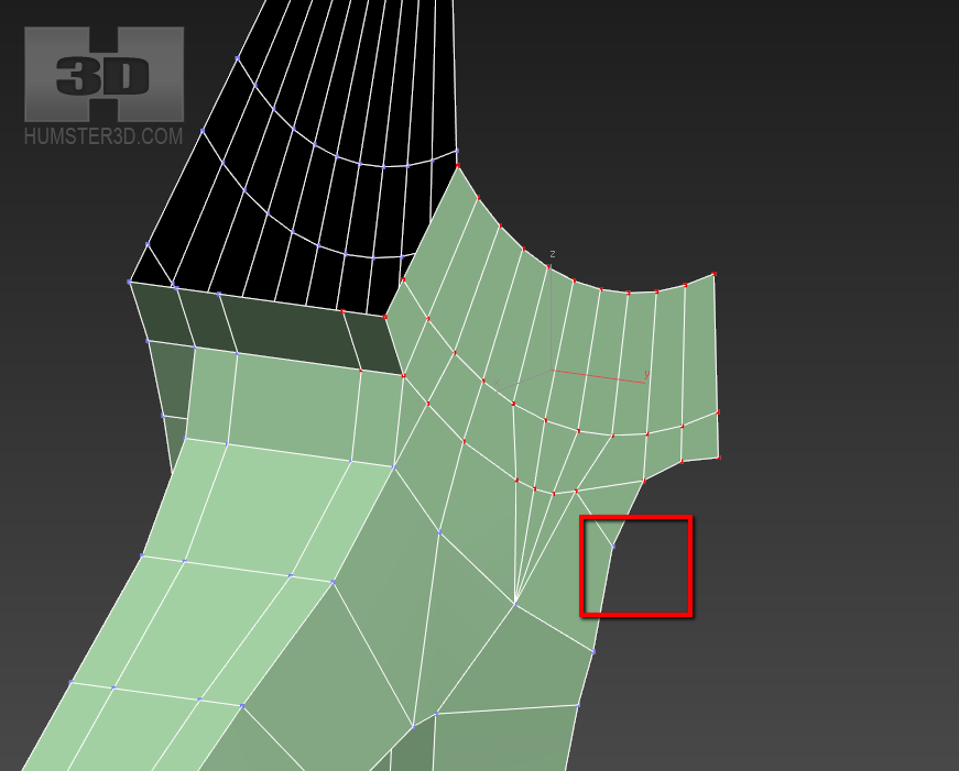
Now it’s time to fix the topology. It is very simple. The main rule is to avoid polygons, which have the number of angles more or less than four and do not make polygons similar to the arrows. Unfortunately, we won’t be able to remove all triangular polygons. It depends on the situation. If the triangle doesn’t do any harm we can leave it. The most important thing is not to use triangles on the bends. You should never lead out any loops on the radial areas of the rim as well, even if it’s quads. You have to leave the original topology of the edge of the rim that was obtained from the primitive of the cylinder.
But how to do this? We need to build some extra loops, where radial loops will converge, which are not made from cap segments. These triangles won’t damage the look, because they are on the flat area.
You should get something like this:
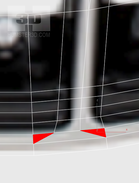
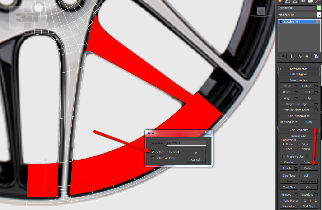
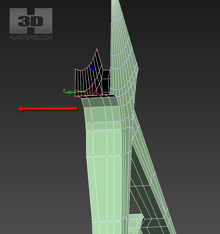
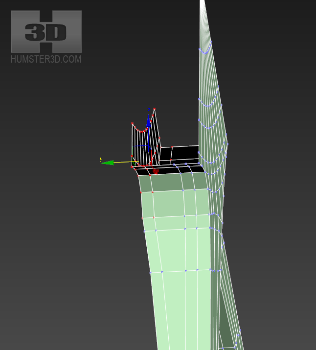
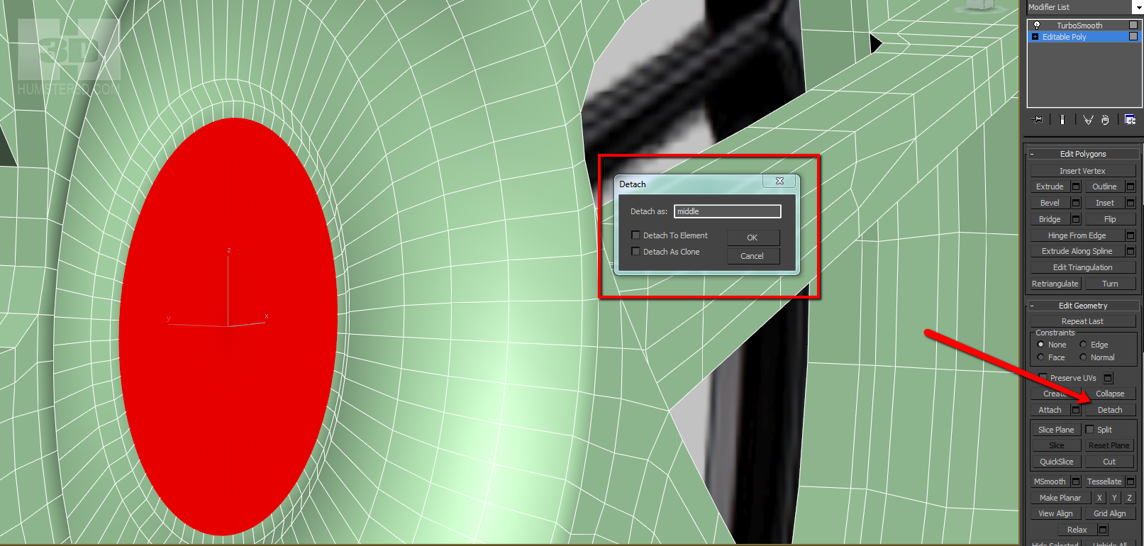
It is time to set a height to our elements. It would be logical to use Extrude, but this function works only by local coordinates and when we collect our rim, we may have some problems on joints. We use Detach to Element and manually set the needed height. Let’s go back to the original rim picture. This picture gives us an opportunity to estimate the height of the elements. Unfortunately, you have to do many things relying only on your accurate eye, so you need to develop it. There are many ways to reduce the intervention of eye estimation, but this lesson is not about that.
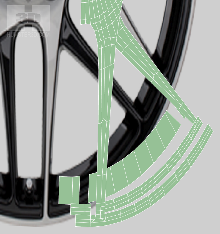
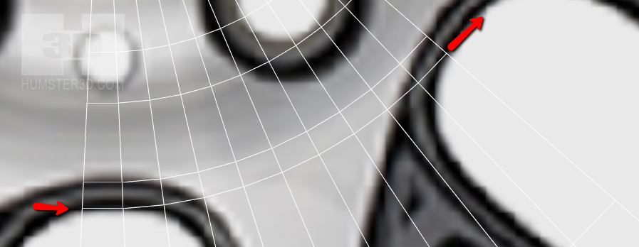
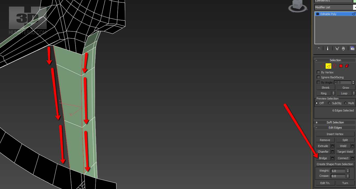
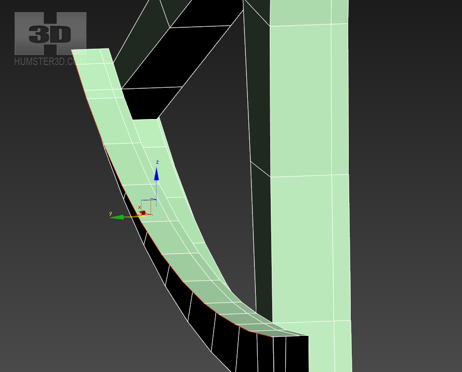
Now our arms are still flat, but they are differentiated by height. Don’t hurry to bend your arms, it will be the next step. Now we need to gather the individual parts of the rim into a single unit. The easiest way is to select all the boundary edges (except those, which limit our segment) and apply Extrude to the edges by pressing shift. If you go to the perspective view of the right, you can activate binding to the points to match new edges with the existing.
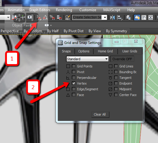
Right click on the mark 1 and enable snap to the points. Left click on the mark 1, it will activate the already configured snap.
Select these edges:
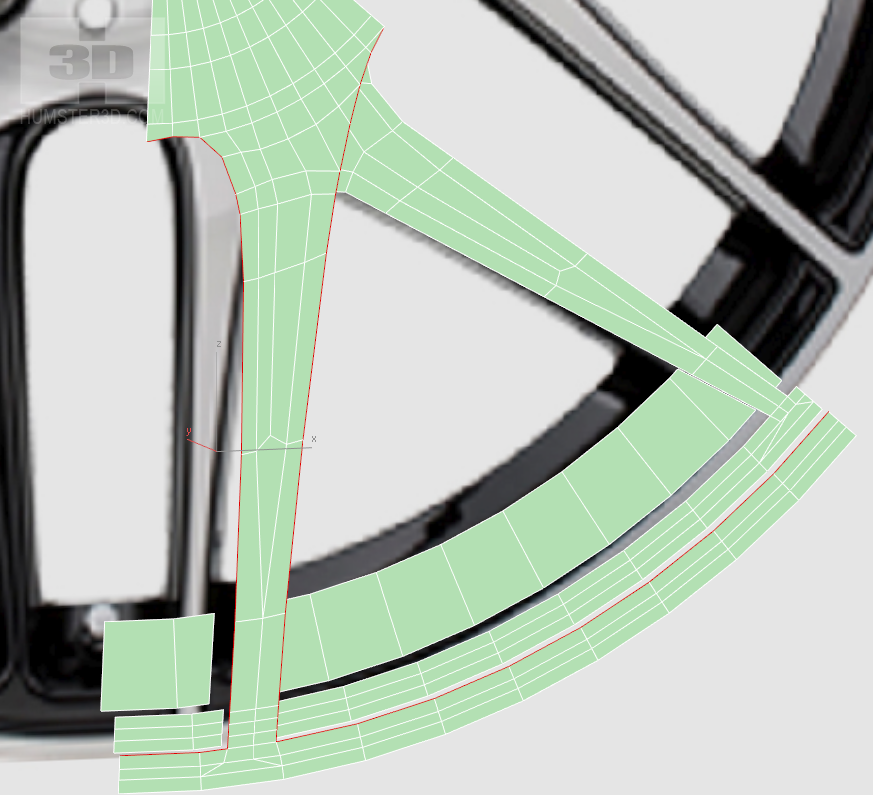
Then go to the right plane, press shift and drag the selected edges. Snap will adjust the new edges to the old.
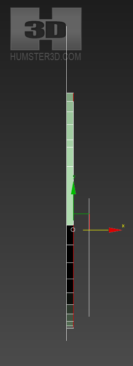
Select all points (ctrl +a) and make the weld, but don’t make too big threshold, in order not to combine unnecessary points.
Repeat the same for the second row of polygons.
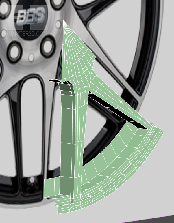
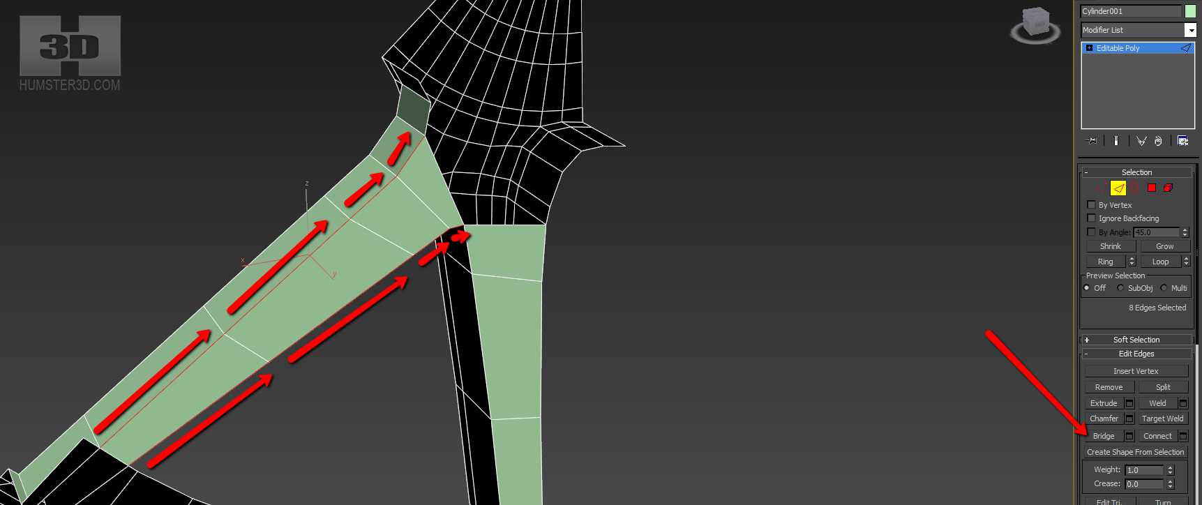
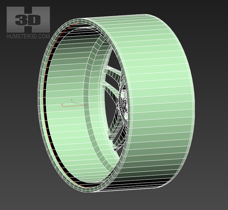
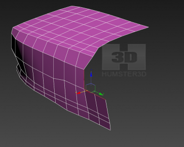
Now do the back side of the arms. This part usually doesn’t fall into the render, so in most cases we just sew it up via Bridge. You have to remember that you can create only one Bridge during the one approach. Select the necessary edges:
Applying the same to the second arm
Now hold down shift, switch on Snap and copy click&drag these polygons. Then press Flip so that the faces of the polygons look in the accordance with the faces of the polygons inside of the arm.
Combine new polygons with the old via Bridge.

Unfortunately, we cannot avoid triangles, but they won’t be a problem here.
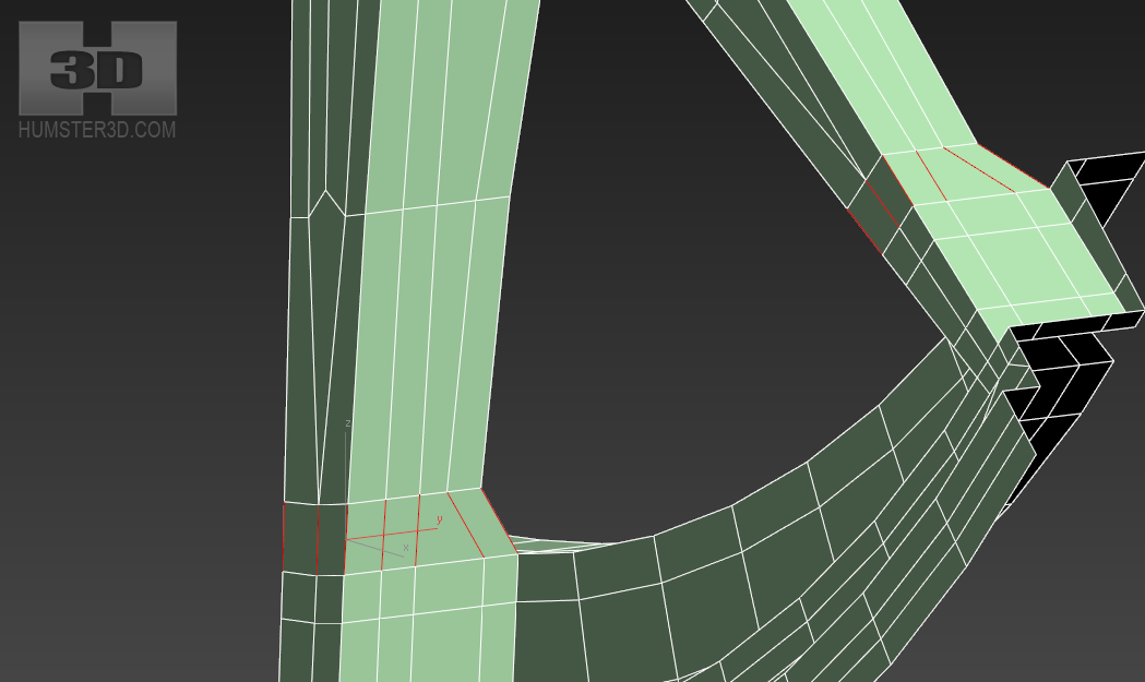
Make the extension of the interior part of the border using click&drag and then we will smooth it.
Add loops here to make it easier to repeat the form of the rim.
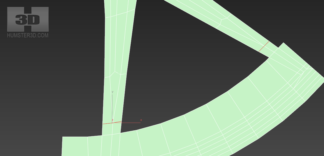
Now let’s apply the different width to the arms of the rim.
For this we select the points and start to move them.
Don’t move points in the square.
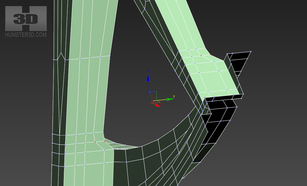
Now the points we have left untouched have to be moved too, so that we can have a nice flow.
Add loops here:
Select Edge ring and add a loop
Move the points a little so after TurboSmooth there will be a sloping surface.

Let’s add more loops on the radius of the arms, so that there won’t be any jumps when bending.
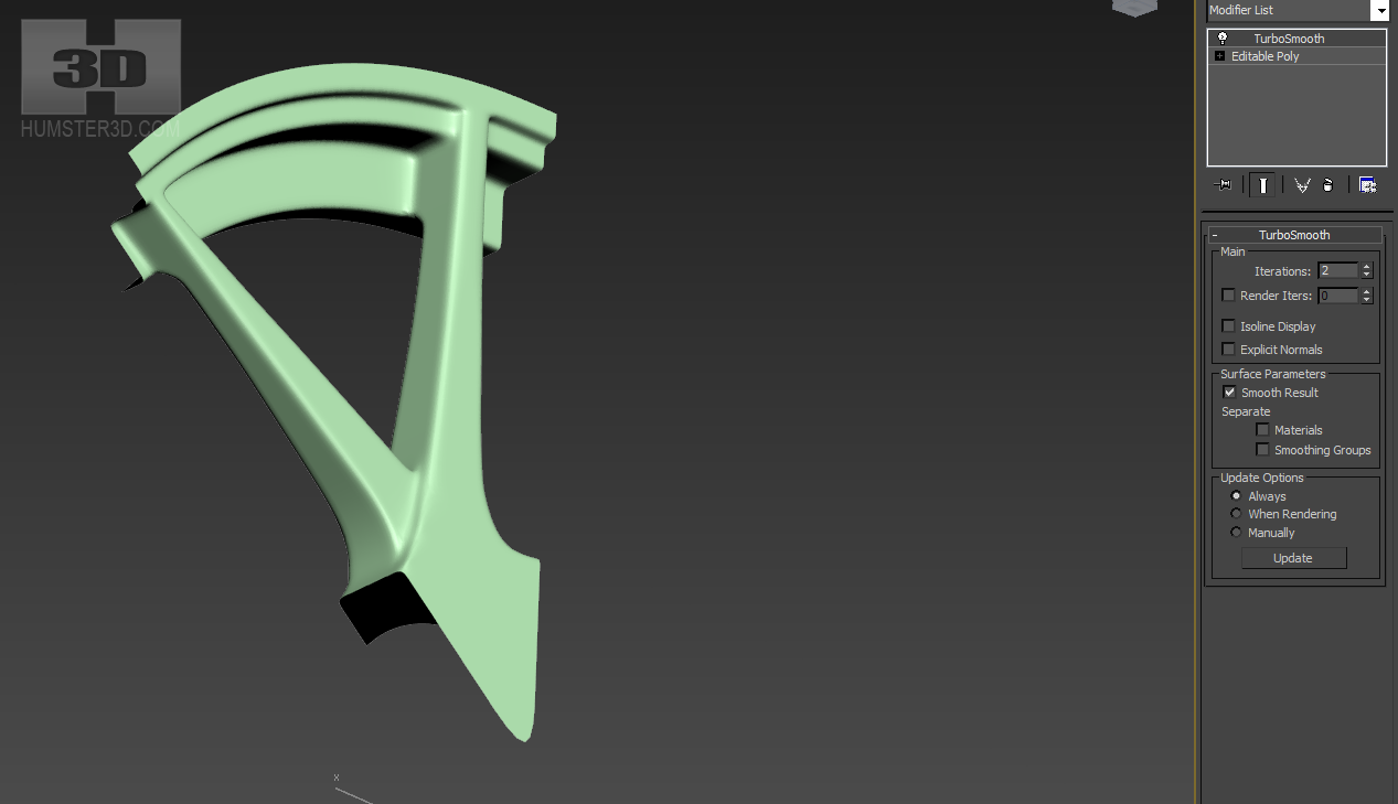
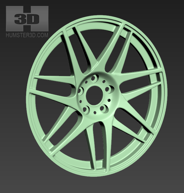
The segment is ready! Let’s check the way it smoothed, for this we will apply modifier TurboSmooth. Making sure that smoothing doesn’t cause any artefacts, we understand that it’s not just a piece of polygon, but a good pattern! It is time to name our mesh.
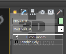
Enter the BBS CX-R in the name of the object.
It is time to put our rim together. There still missing nut holes.
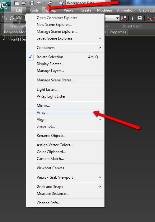
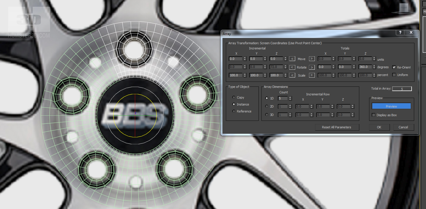
Remove TurboSmooth, because it’s not useful now. Create the array.
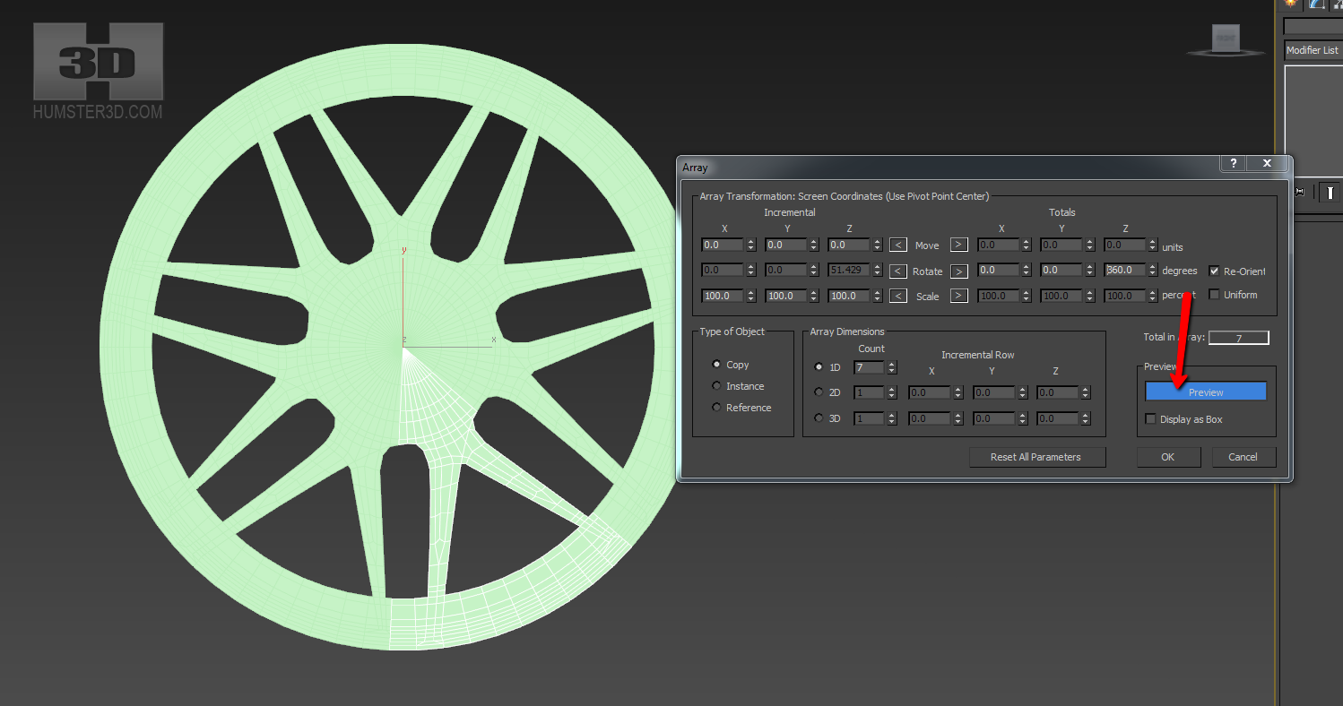
Select the parameters of array to form the entire rim. In our case, it looks like this:
You can immediately see any changes by activating Preview button.
Select your base segment, press Attach and select new segments.
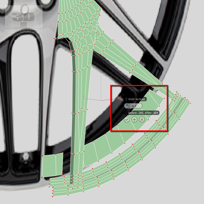
Now we have to combine component parts. In order not to affect extra points, go to the mode selection border, select all borders, press ctrl and click to select points.

By that, you will select only those points, which belong to these borders.
Then weld, but don’t overdo it with the threshold, so as not to lose details.
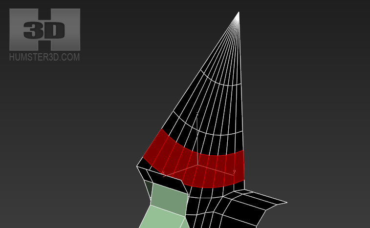
Now let’s make the recesses for the nut holes. Select these polygons and move them back a little.
Enable TurboSmooth to see how your model is smoothing. Add the loop using flow connect, the technique described above.
Make a small rise near the central hole. For this, we need to add loop here:
Select these polygons

And move them a little bit forward.
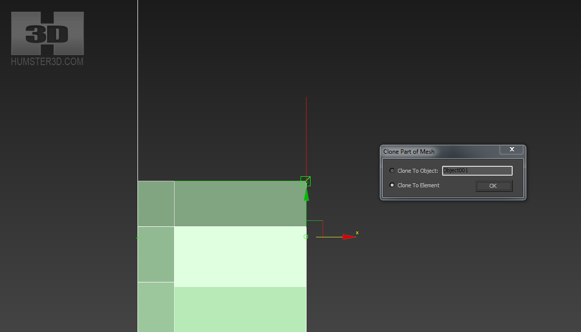
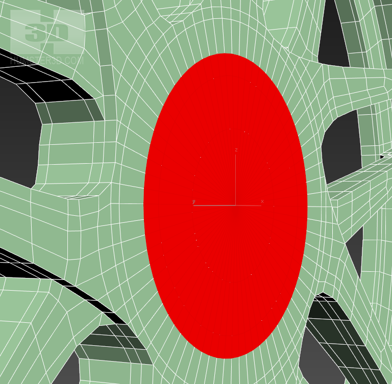
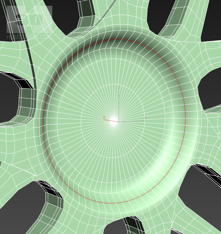
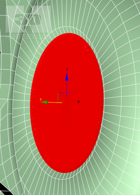
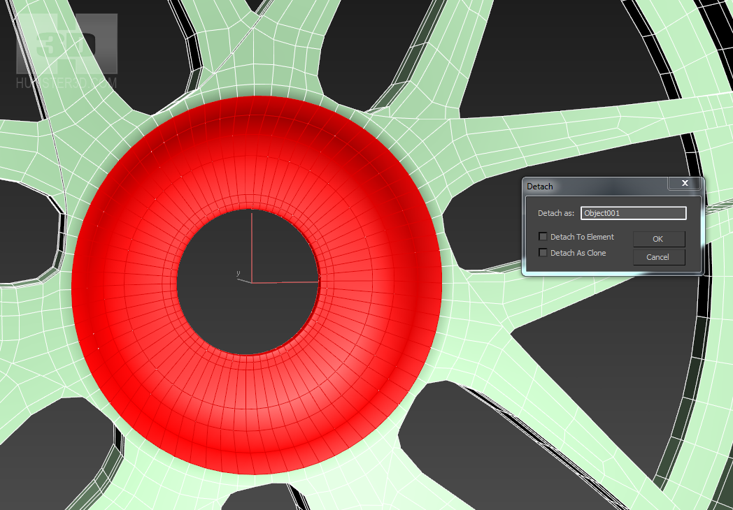
Separate using detach the central hole, but this time into a single object.
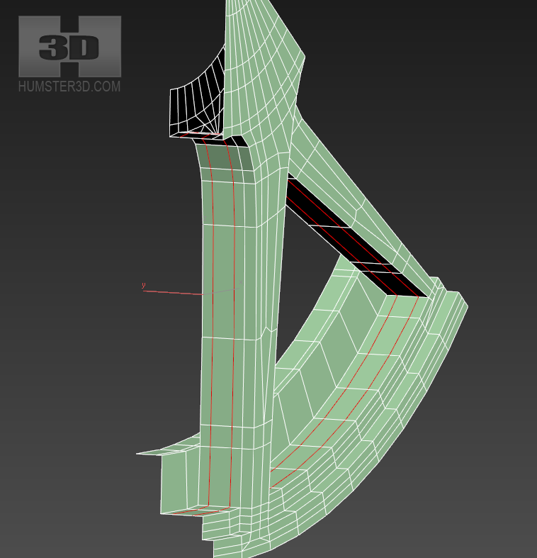
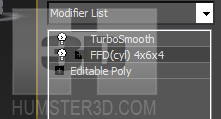
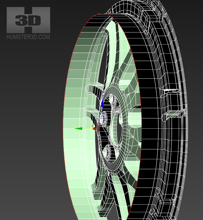
We need to set the curvature to the arms before slicing the nut holes. You have to do this before slicing, because the holes can get deformed. That is why we need to apply modifier FFD(cyl).
You have to do this in a way so that TurboSmooth was higher in the hierarchy. Please note that FFD(cyl) distorts a mesh. In order to avoid this you need to use the same number of segments as in the original primitive. We had 70.
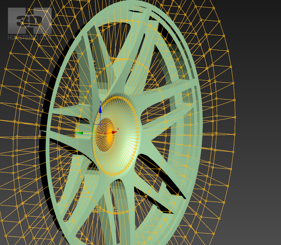
Go to the control mode of the FFD (cyl).

Select the points along the line of the circle and begin to move them back a little bit.

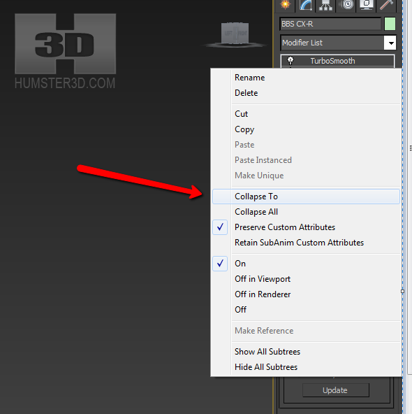
Then right click on the modifier and press Collapse To, so it couldn’t affect our TurboSmooth.
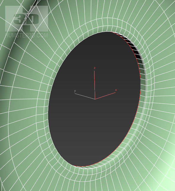
Immediately do the welt by the central hole using click&drag.
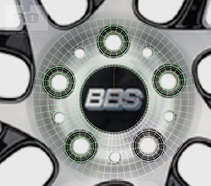
We need to separate the recess for the holes, if we don’t want to do 10 holes at the same time. Let’s make one and then duplicate it, as we did with arms.
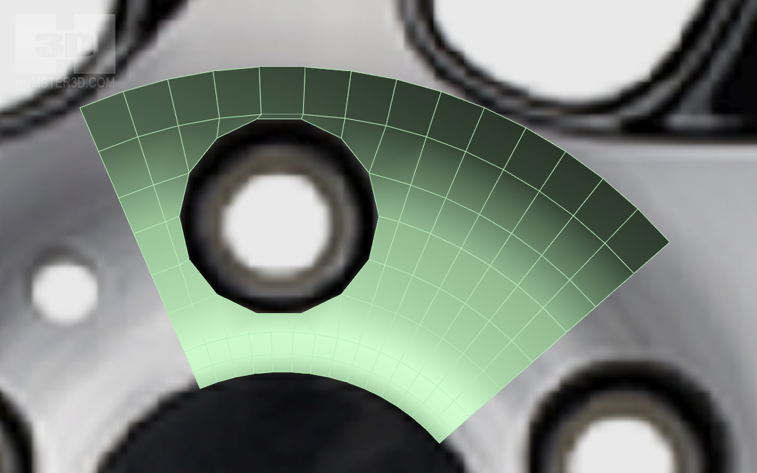
We have 2 pairs of holes, 5 pieces in each, so we need to separate 14 segments, 7 for each hole. Let’s check
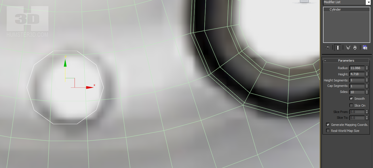
Create a new cylinder and adjust it to the hole. First, we are going to make a big hole.
Now outline the hole using Cut with enabled Snap. Just draw out the cylinder. Thus, we have projected the cylinder on our mesh.
Align the topology and remove unnecessary part. Use click&drag again to create the hole with welt.
Align the welt align with the Z-axis. Make the interior of the hole by the same method.
Create an array from that piece, but this time choose copy method Instance and 5 elements, so the objects have duplex connection.
Make the second hole in the same way
As you can see, the hole has immediately appeared in all segments.
Combine it with the rim. The method has been described previously.
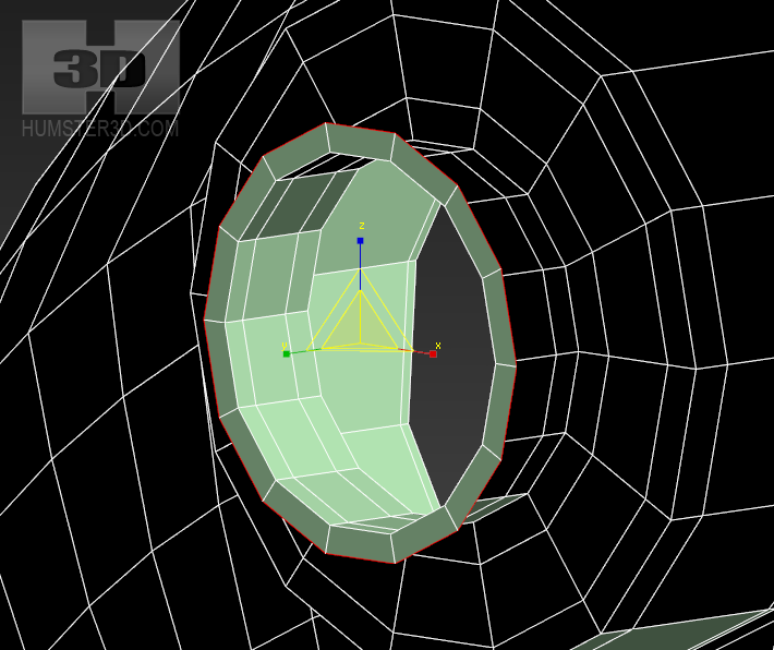
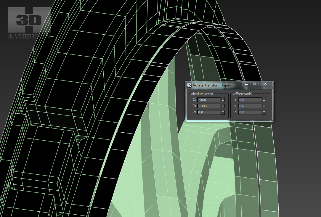
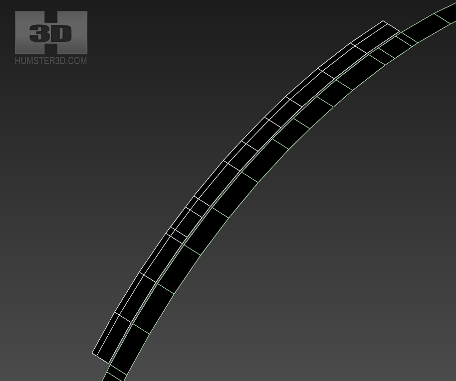
Now we need to put our interior rim in order. Separate the inner rim and rotate 5, 143 degrees. Unfortunately, 360 is not divisible by 70 without the remainder, so we have to be satisfied with rounding.
Make another loop, where we are going to align.
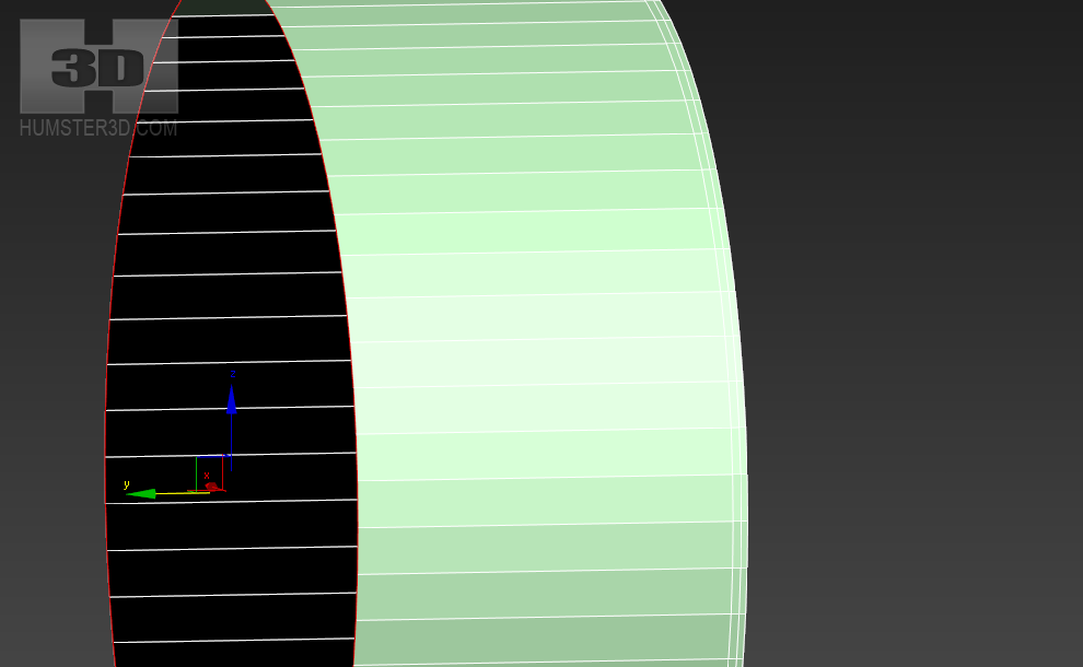
Now separate the inner rim to avoid repeating the same actions for several times.
Create an array of segments again and combine
As you can see after the smoothing, everything is all right.

We need to finish our rim, here is the order click&drag:
Now you need to make chamfer in these edges
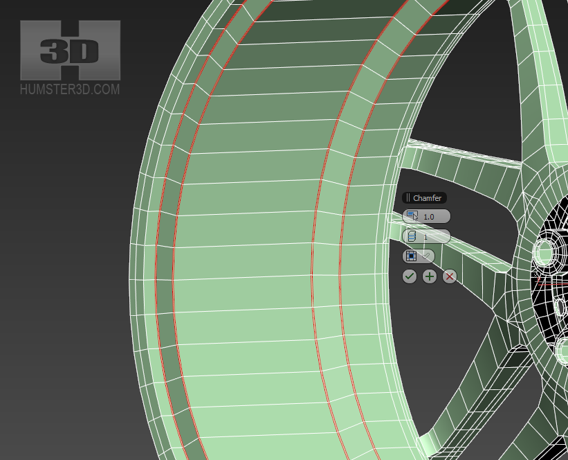
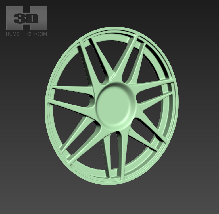
Here we have such a rim
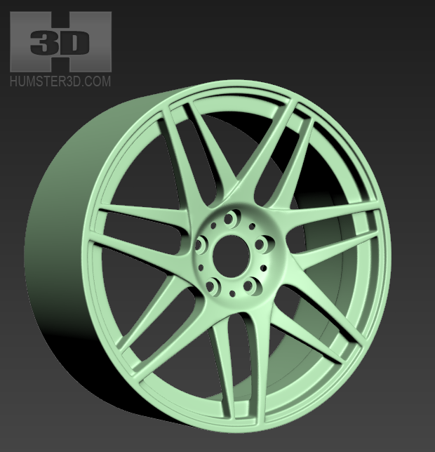
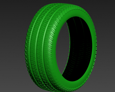
The external border of the rim doesn’t have to be detailed more if it is closed by the tire. To make it look more convincing you need to add nuts, top on the central hole, pin, insert everything in the car and make a render. The break system won’t be superfluous.
The place for the render we will do afterward.
So this is it! The rim is ready. Everything else is just details and now it’s such a trifle for you!
Have a good render.


)
uouu Perfect!
very useful. thank you for making this tutorial.