
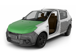
 Carros
 Caminhões
 Autocarros
 Motociclos
 Militar
 Eletrônicos
 Armas
Armas
 Edifícios
 Aeronaves
 Móveis
 Personagens
 Animais
 Nave Espacial
 Alimentação
 Navios
mais
Hello everyone! Finally, we can continue our lesson. Now the time has come when I’ve already clarified all theoretical subtleties and at this stage we have a lot of routine work ahead. We’ve promised you that we wouldn’t miss a single moment in this tutorial. Therefore, while going in for routine manipulations, sometimes I can repeat myself. Nevertheless, you shouldn’t take this information for “I’ve seen it in the previous episode”. The constant repetition is the mother of learning. Think of it as a kata. With the help of monotonous katas an apprentice turns into a sensei. So let’s achieve a black belt in 3D modeling!


Arigato!
Hajime!
We select all these edges at the back part of our car and remove them using “crease”.

Our Lancia is quite a non-typical automobile. We can say that it’s made of separate modules. On the one hand, we should cut the model into sections at the very end, but, on the other hand, since it is composed of modules, we’d better divide them now.


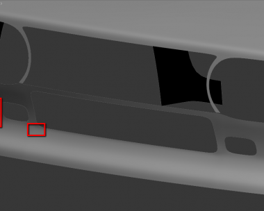
So far we won’t go cutting it any further, we always have plenty of time for it. We create additional edges to keep the shape with the help of “extrude”.


After applying “extrude” this place has a wrong topology.


Here we add new edges in the same way.


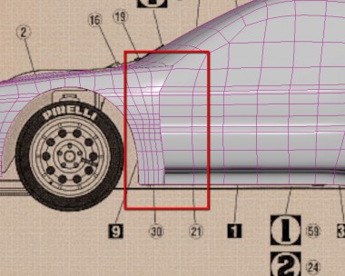
It’s high time to make this ledge.

For this we need to compact the rear bumper grid. All new edges should blend harmoniously. That’s why we resort to the trick with “flow connect”, which I described in the previous lessons.


And now the ledge itself.


Once you select these points immediately apply modifier FFD (2x2x2). Just make sure that the points are chosen – the effect of this modifier should be directed only on the given points.


Drag them a little bit down.

We need a very small bending flexure.


Here we have an annoying place. Its modeling won’t be easy at all. Two hard edges intersect and then become smooth. It’s quite complex and difficult to reproduce, so I advise you to create a backup copy of your model.

First we create a horizontal edge.


Now the edge on the roof.


Here you go! You should come up with something like this.

Please, notice, that edge A is harder than edge B.

To do this we just need to select this edge loop and press “set flow”.


Before:

After:

And we continue.


Here we have a point that broke out of the picture. Drag it a little higher with constraints on edges.


So far mesh here is nice and smooth, but soon we’ll make a cut for the windshield and some twists are going to appear.

But we increase polygon density here beforehand in order to minimize the effect from cutting the piece of geometry.


Now we separate the side window.

Drag a bit the detached piece in the center.

We need to add more edges along the body, but on the door the ribs are much harder than in the rear part of our car. That’s why we separate the doors.


And now let’s, actually, create new edges.


Please, pay your attention that here the curvature of body panels on the doors and on the wing differ.

The easiest way now is to drag the points manually.


We have to check that curvature here is accurate by eye.
The next our step is to outline the windshield using cut tool. Here we a have one more peculiarity. Since our blueprints don’t converge with each other, the roof rack will be our guiding line.


After we clear the space for air intake we can separate the rear window.

But it will be in the next lesson as for today it’s enough.
My congratulations, fellows! We’ve taken another step towards our goal.
Have a nice render!


.)
When will be next part ?
We hope soon, but don’t know when :(
Please, when will be next part? This tutorial helped me a lot , and I wish there was more to it!