

 Автомобілі
 Вантажівки
 Автобуси
 Мотоцикли
 Озброєння
 Електроніка
 Зброя
Зброя
 Будівлі
 Авіація
 Меблі
Меблі
 Персонажі
 Тварини
 Космос
 Їжа
Їжа
 Кораблі
Теми
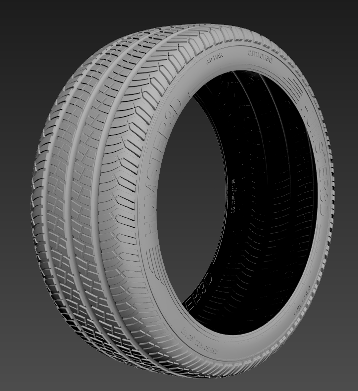
Hello, guys. As you may notice from the title today we will discuss creation of a tire in 3DS Max. After this lesson we will put our drive from the previous lesson into a new tire. But in this lesson among the tire creation we will design detailed welt. Without this specific the tire will be incomplete.
So, let’s start. For the beginning we should find an appropriate reference. Our tire will be build-up as the search of new references takes a lot of time. If you don’t chase the goal to create specific model of tire, then in suits you as well.
Otherwise you should find blueprints of a required model.
After brief search we wind a picture that is similar to this one
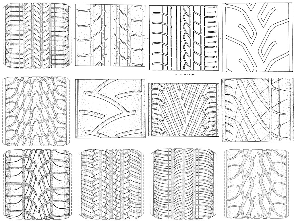
and choose the most appropriate tread pattern. I’ve shown you in the previous lesson how to download blueprint into viewport of 3DS Max. I think this tread pattern fits the best for our lesson.
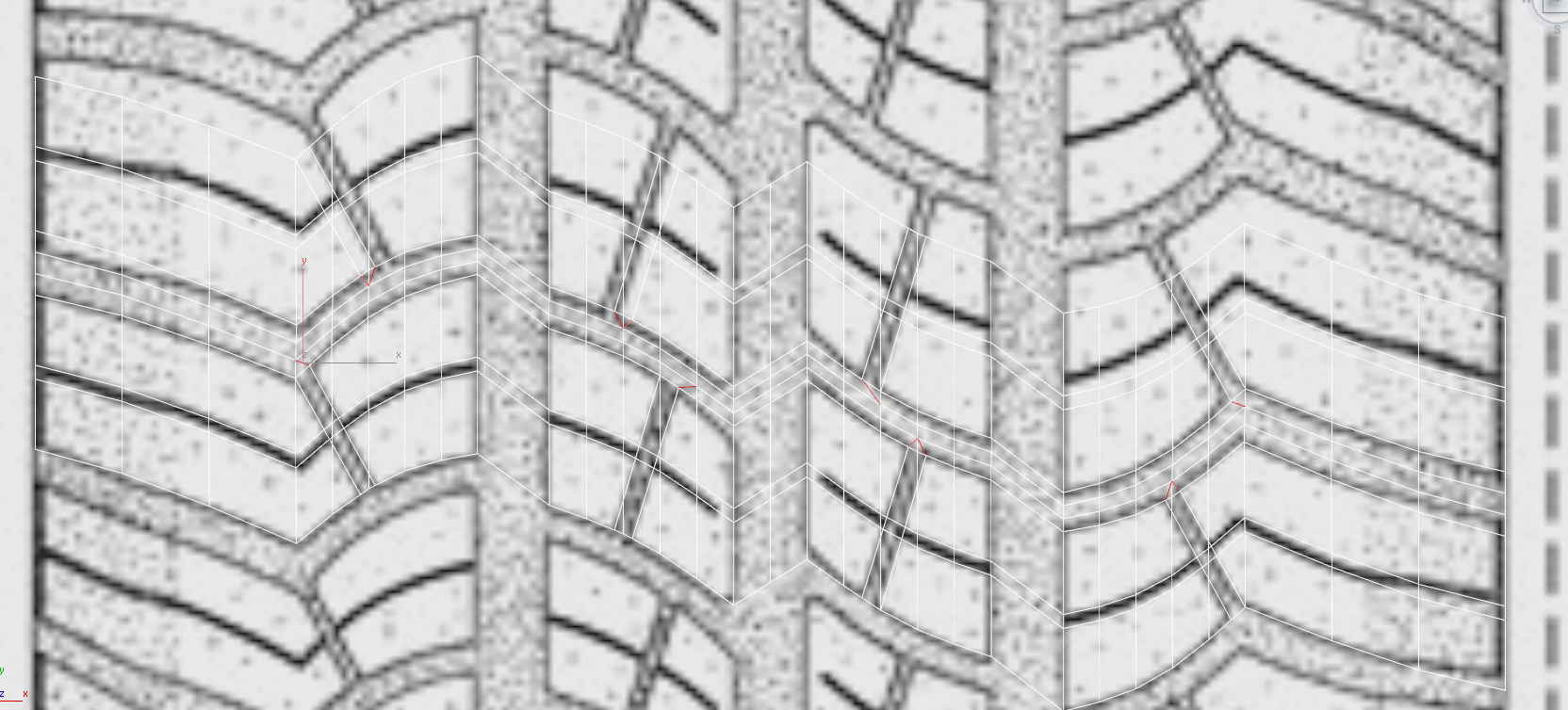
Now we start modeling the tread. First we simply plot its form, fur later we should use a certain trick of which I will tell you later this lesson.
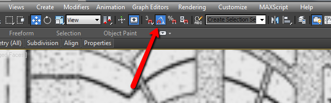
Create a usual plane and convert it to editable poly.
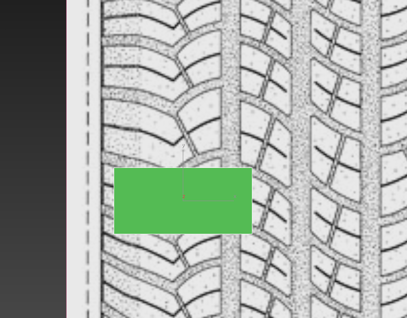
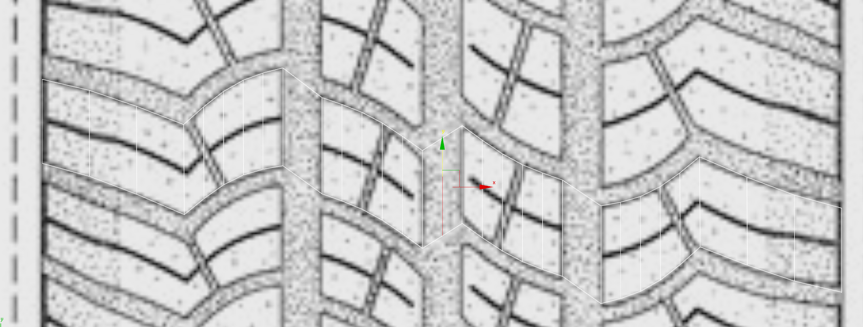
Further using click&drag we plotting the required geometry. We need to model only one strip with treads – the rest we will get using doubling.
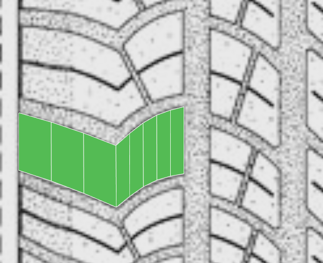
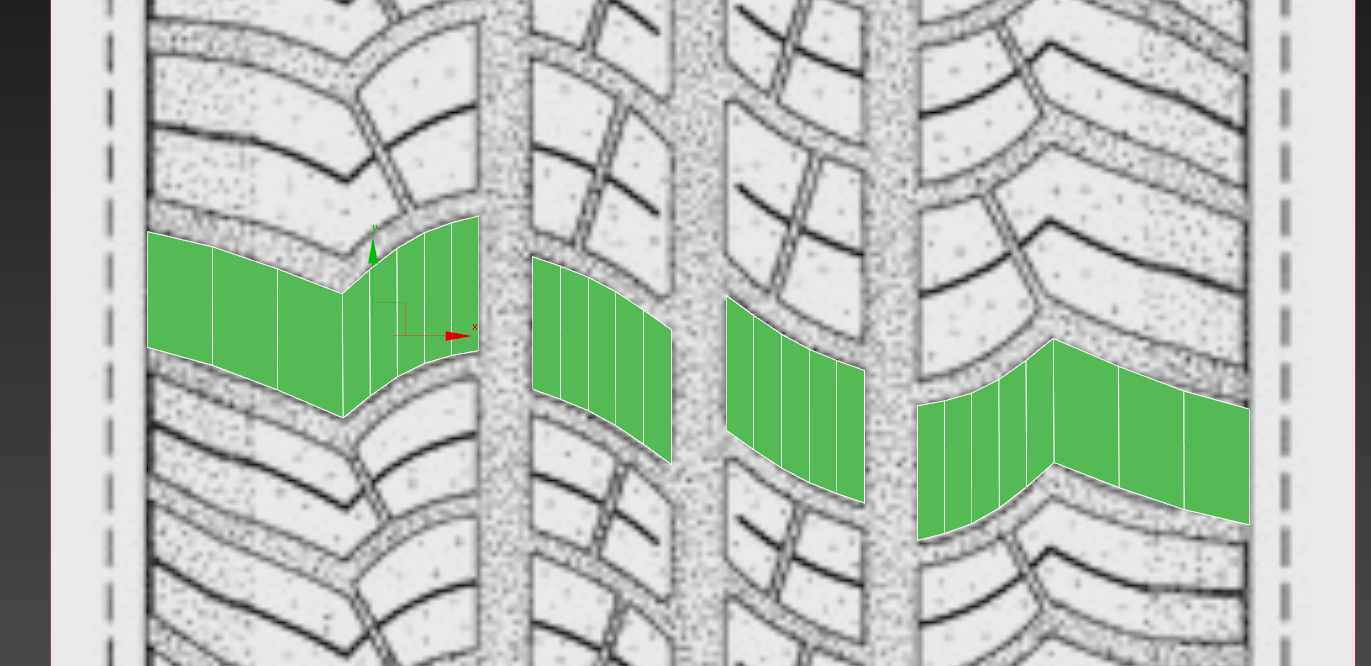
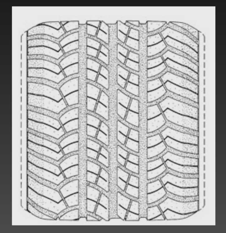
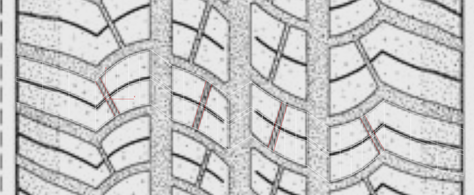
Please pay attention that pattern’s sector is symmetric about a central point. You may simply copy and rotate a part of a pattern. But you should be careful and don’t forget the inclusion of the angular anchor. Besides not all tires are symmetric so this is rather the exception than the rule.
Basing on tire’s symmetry we will delete one half soon and now we need it to make our profile equable. Crosslink the treads using bridge.

As well we should make the rib at the point where we an axis of symmetry lies.
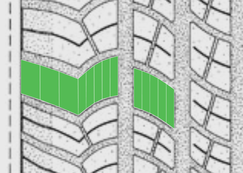
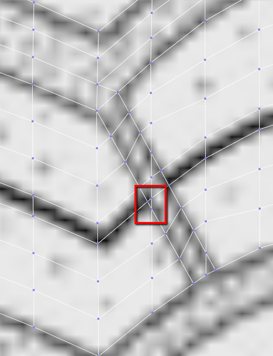
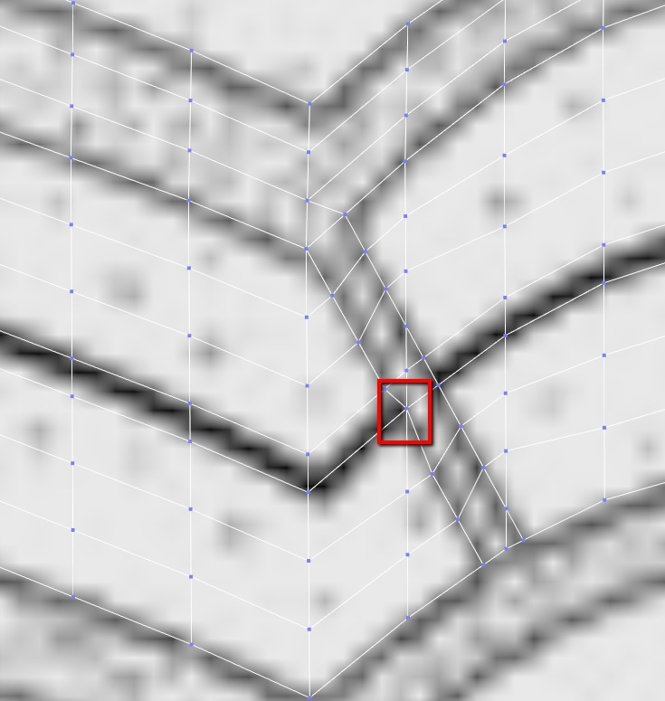
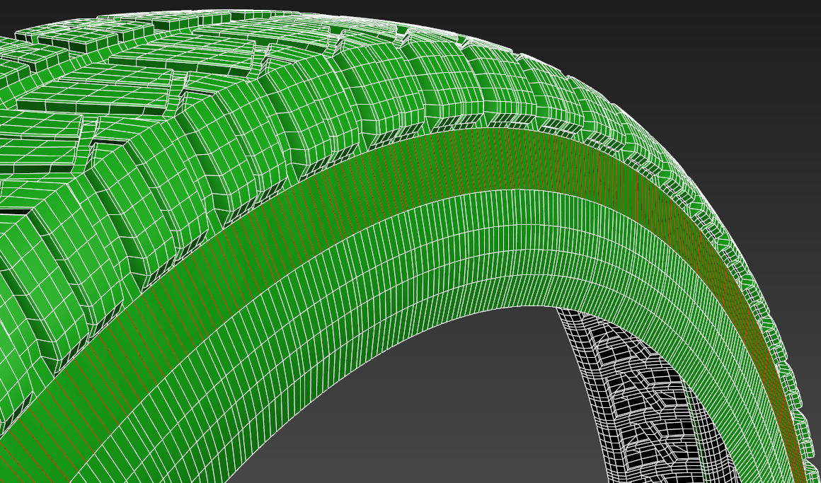
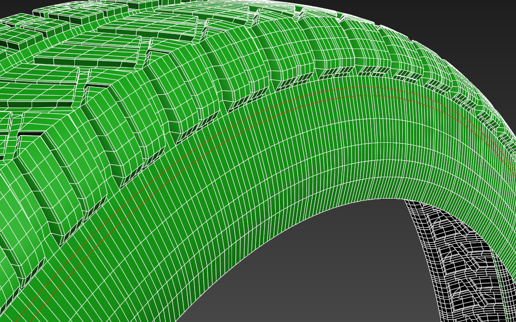
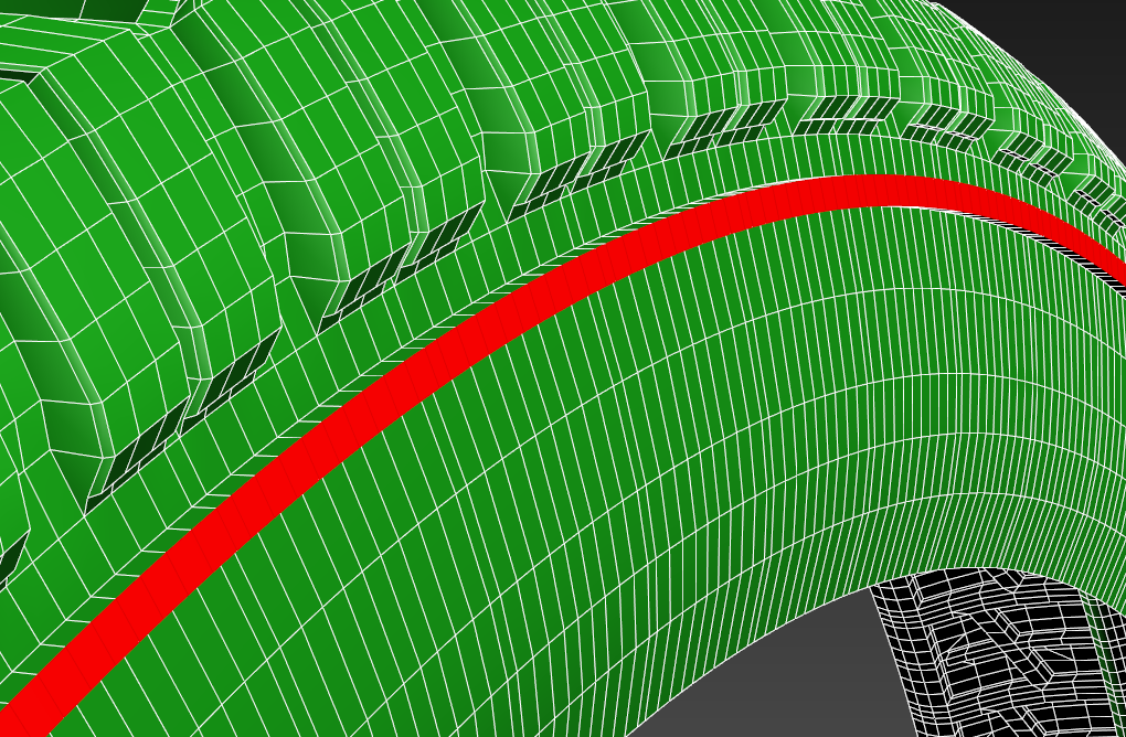
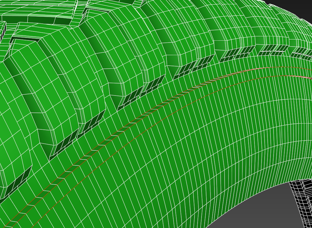
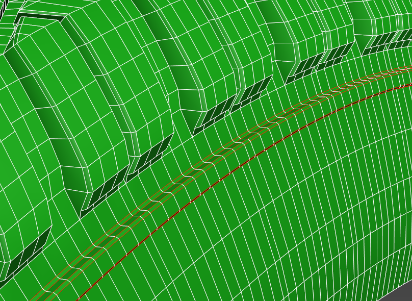
There is a strip in the middle of a tread that separates it in 2 parts. We should make this strip right away. By the way we have not given geometry of our treads quite.
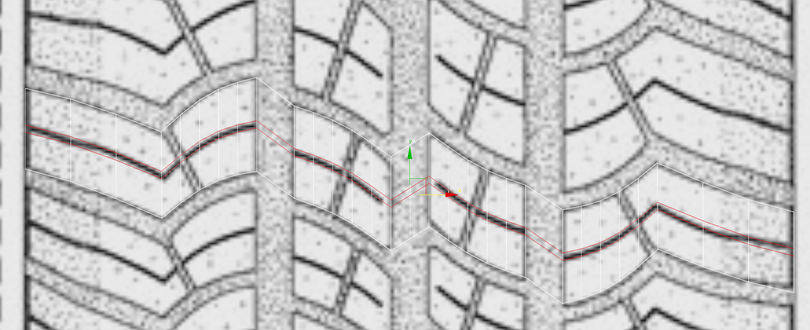
Pay attention that loops on the bottom edge from the point of view of the observer do not correspond with loops on the upper edge. To fix it we double the segment up to get our loops in order.
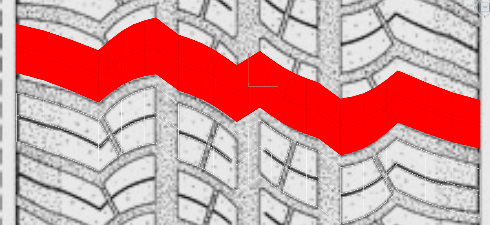
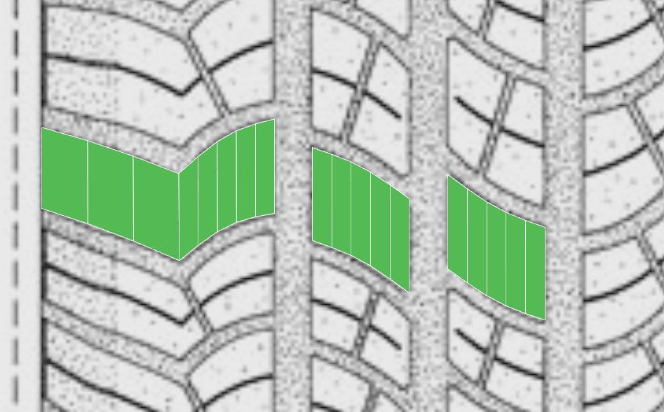
We crosslink them in a way to get the new ribs only where they go strictly vertically.
Now we make connect for 2 elements.
Next get rid of the polygons where there are more than 4 apexes. Do not worry for the triangles our tire will be without turbosmooth.
We delete the upper segments of treads so they won’t interfere us.
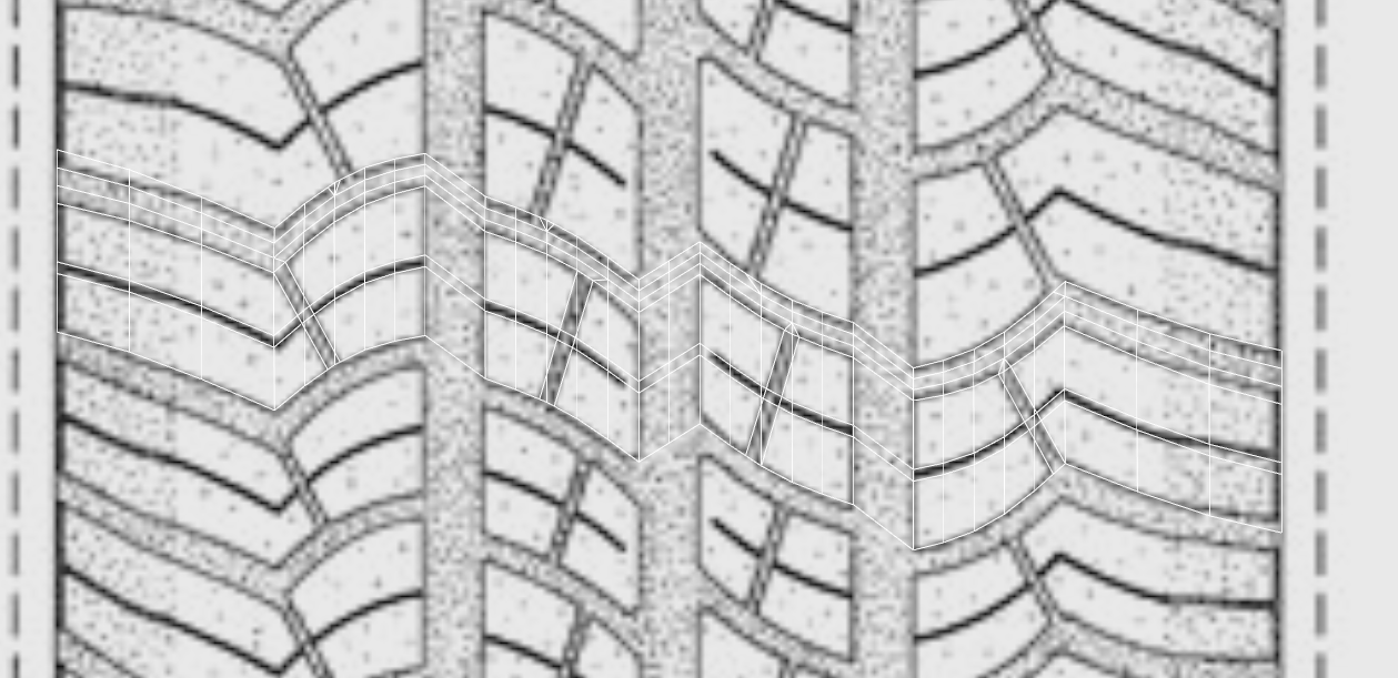
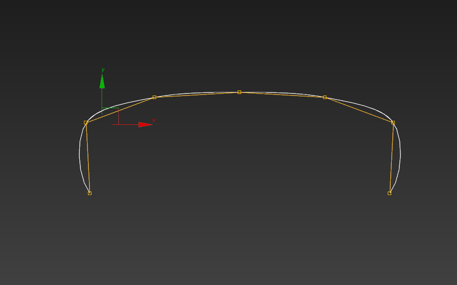
As the tire is round we make the flat tread. We should flex it with bend. And we should divide our protectors at 1 segment, better 2 segments, to avoid the flat look.
Please count the fact that the central treads are not divided by the center line to the fullest.

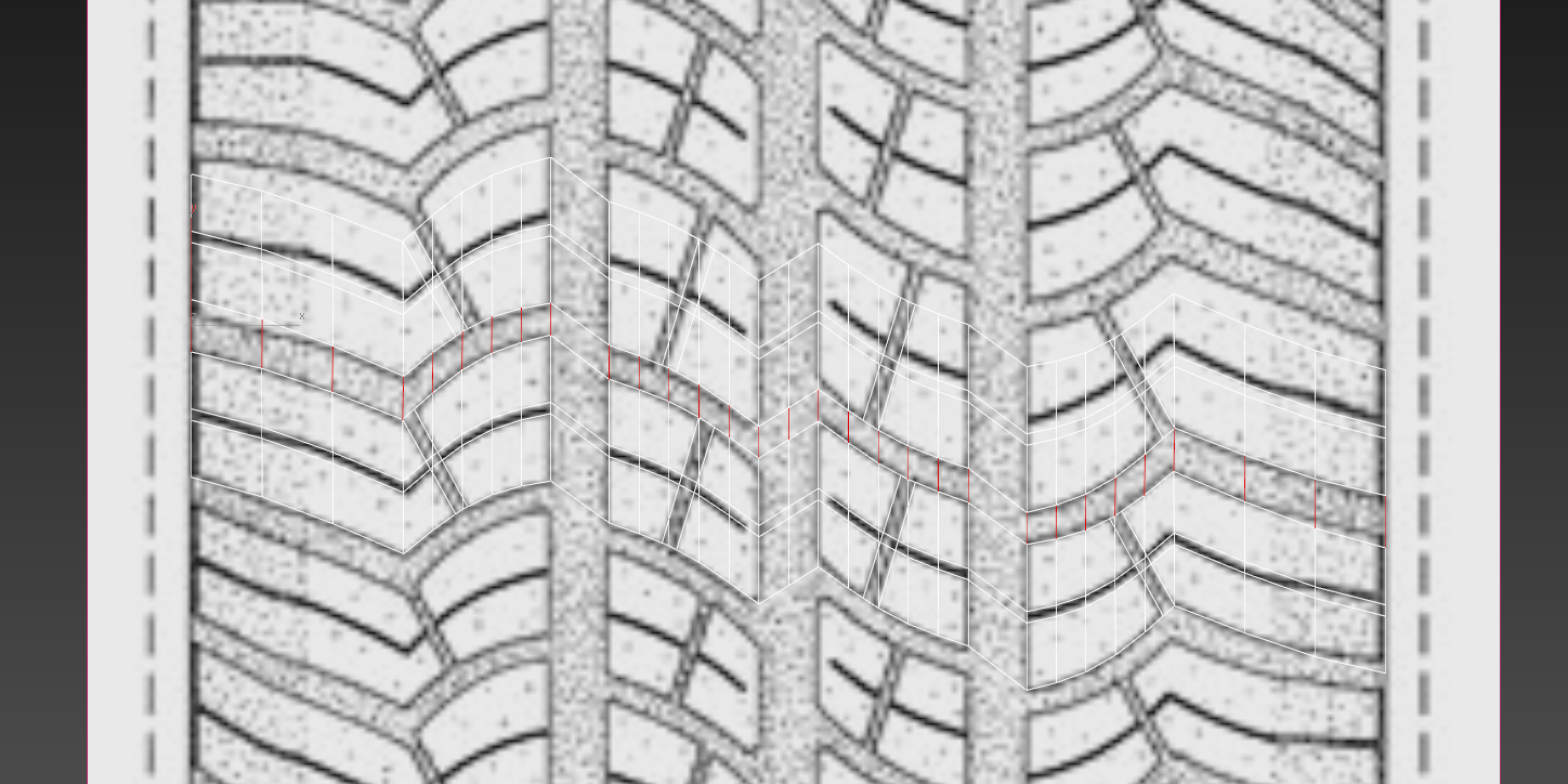
Add loops into side treads to make the polygons equable.
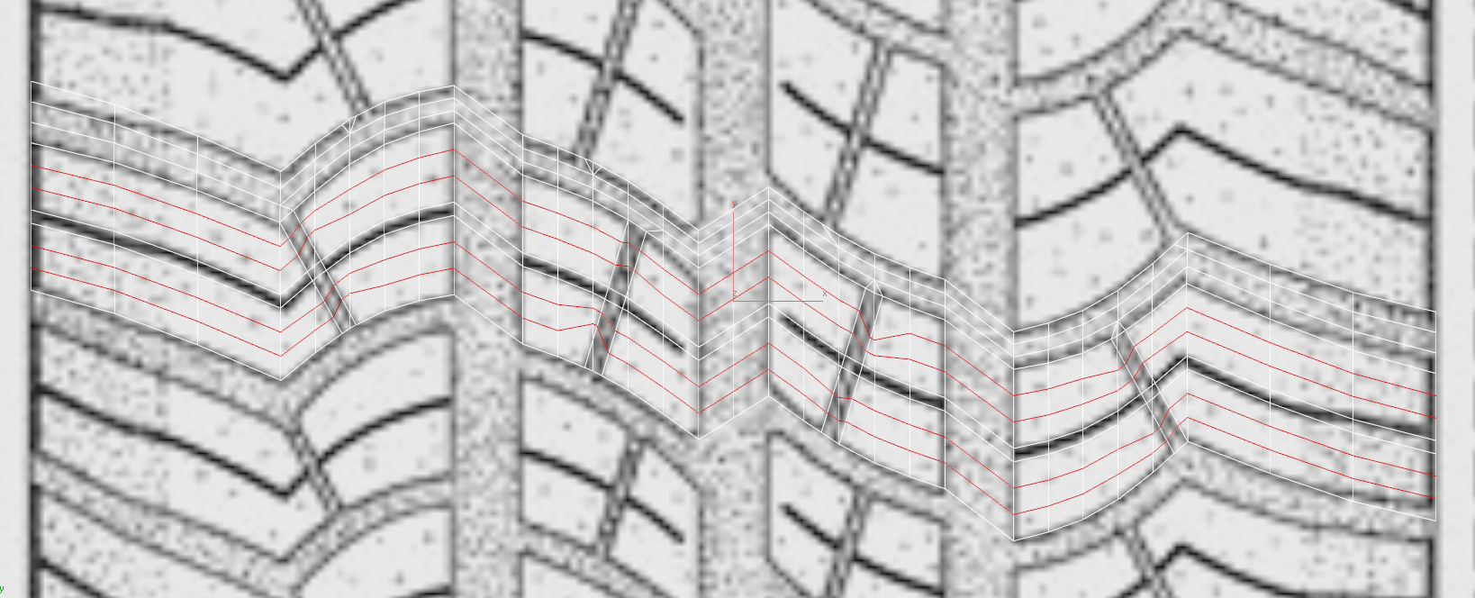
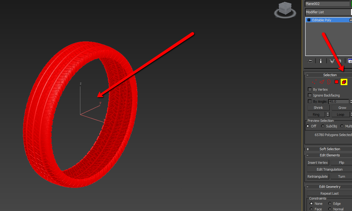
Actually we have given the required geometry and may start the final part. It is time to fix topology. We need to eradicate these little polygons otherwise it will be inconvenient to make chamfer on the tread’s edges.
As a result we should get this like mesh.
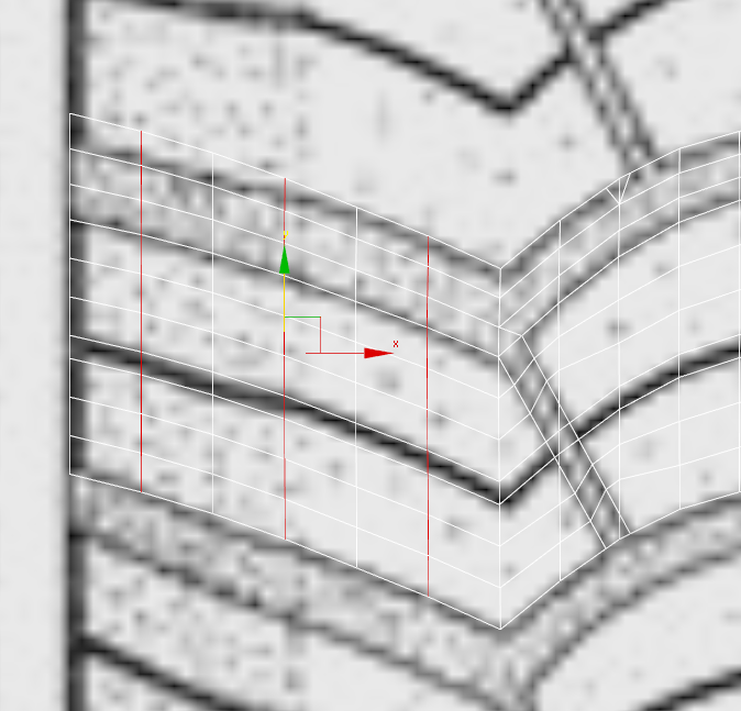
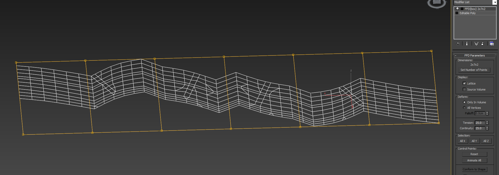
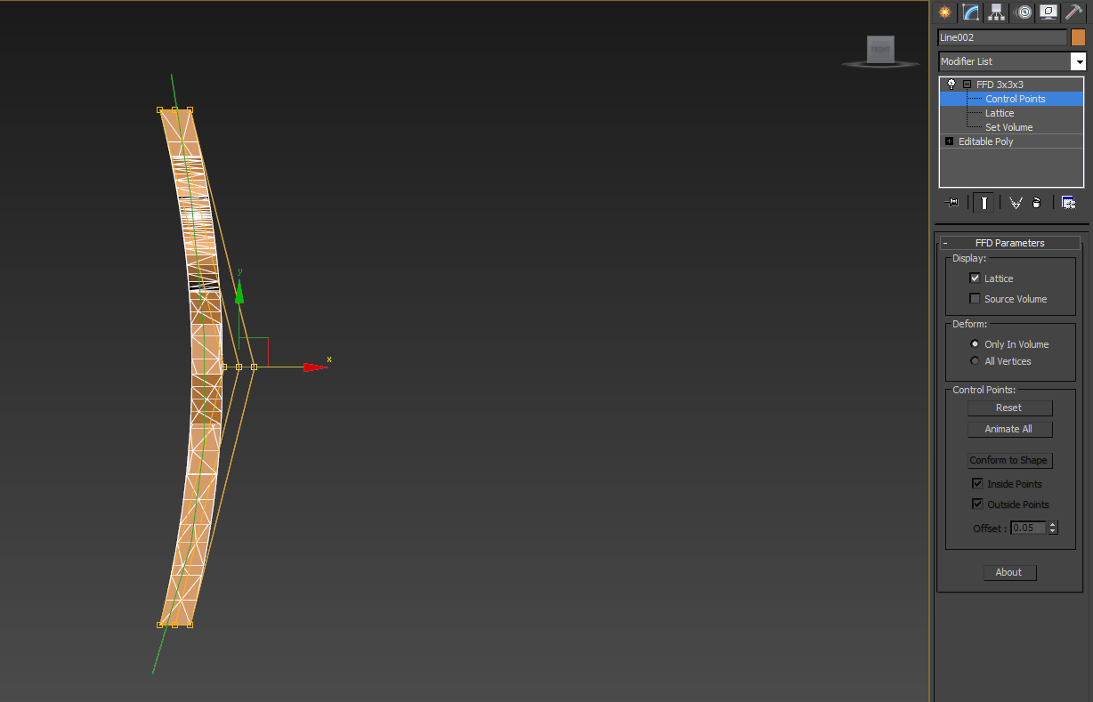
Now we should specify the required curve of the profile. Do it using FFD. It is enough to divide into 7 parts.

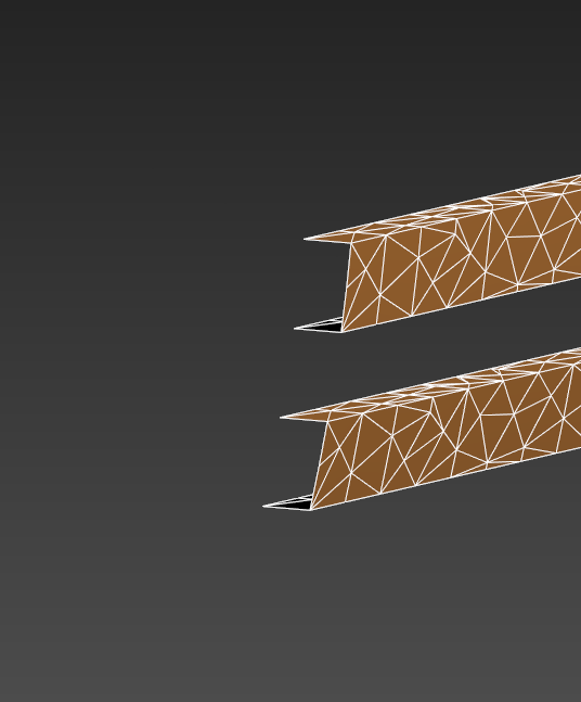
The time has come to press out the treads. After that our tire starts to get the shape. Allocate the polygons that have need already prepared and press extrude.


Further press and hold shift and press the icon of picking ribs to choose the ribs on the edges of located polygons.
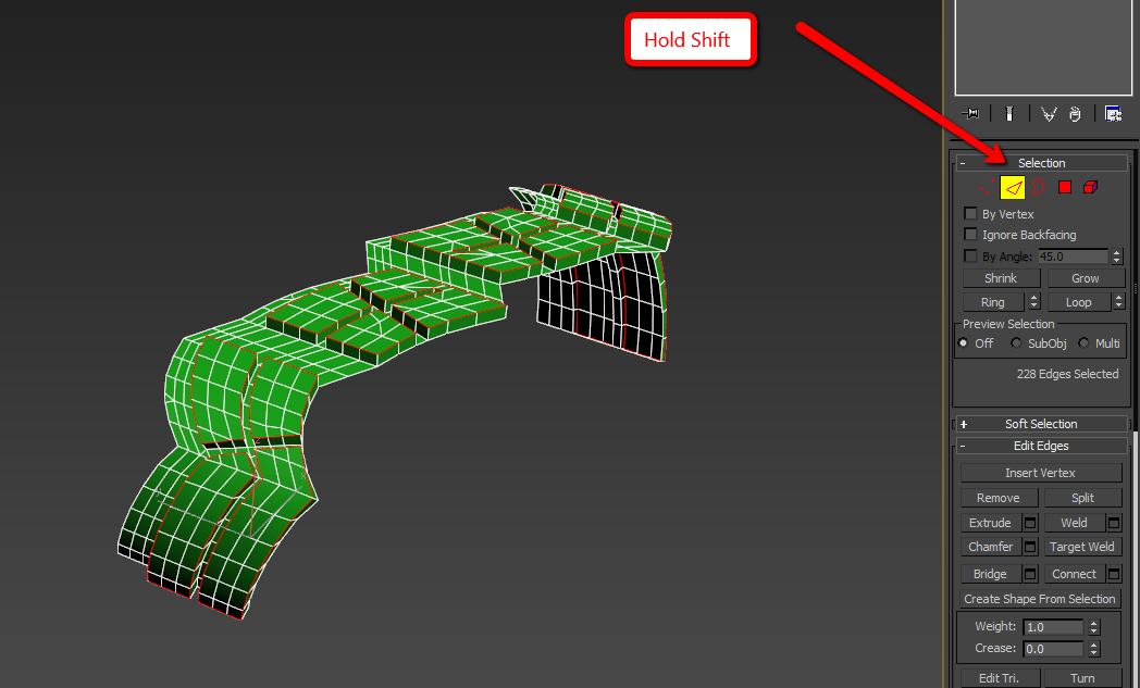
Now let’s do chamfer on these ribs on 1 segment.
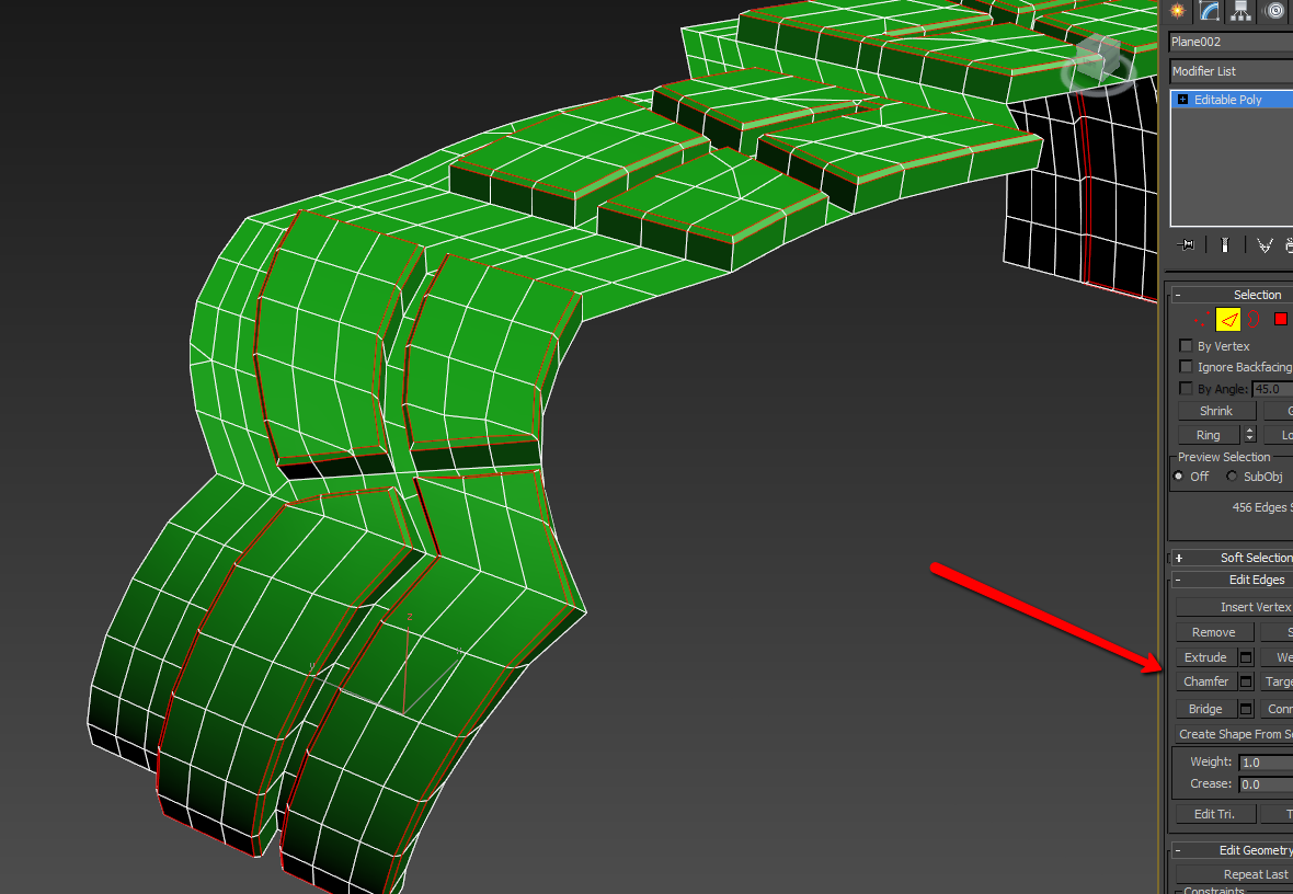
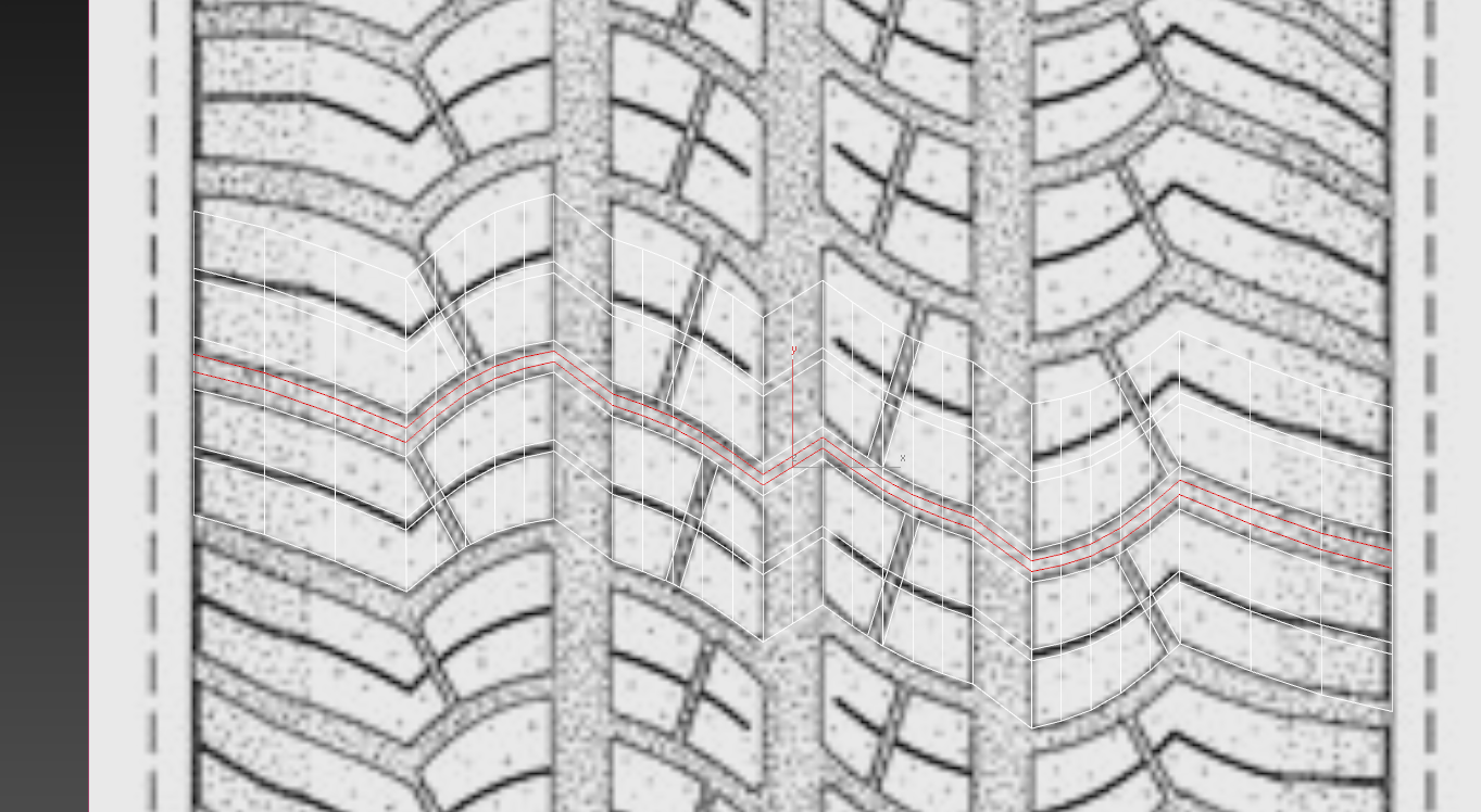
Let’s make a deepening between the treads at once. To make it we divide the ribs along the deepening using connect.
And get down the resulting polygons.
Let’s make a little chamfer to smooth these polygons.
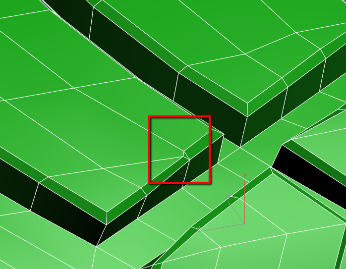
Pay attention that after chamfer on the edges of treads there are parasitic polygons. Let’s fix it.
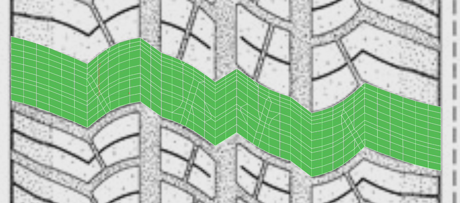
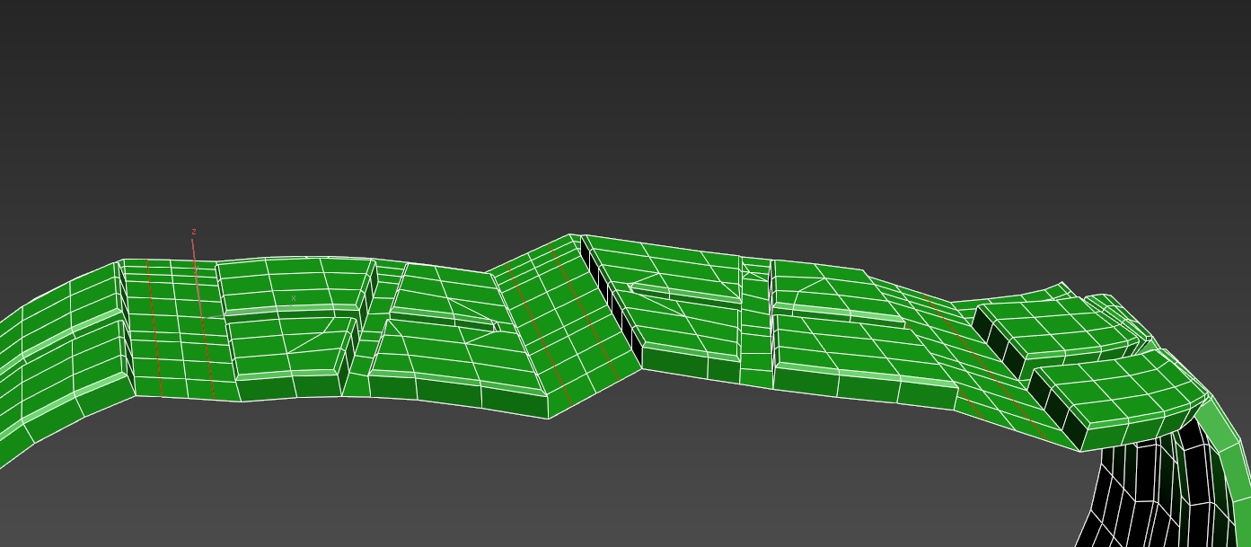
Segment is ready! It is left to double it, crosslink and flex. In the average one tire consists of 60-70 but this number may vary in some tires. Let’s make 65 tread’s segments. Include the linking as we did in the previous lesson. And using click&drag double 64 times our segment as 1 we already have.
Wait until this like cross appears near the apex.

And pull along with the linking to appropriate apex in the other edge of the tread.

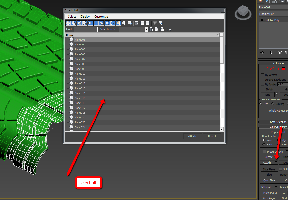
Now attach all new objects.
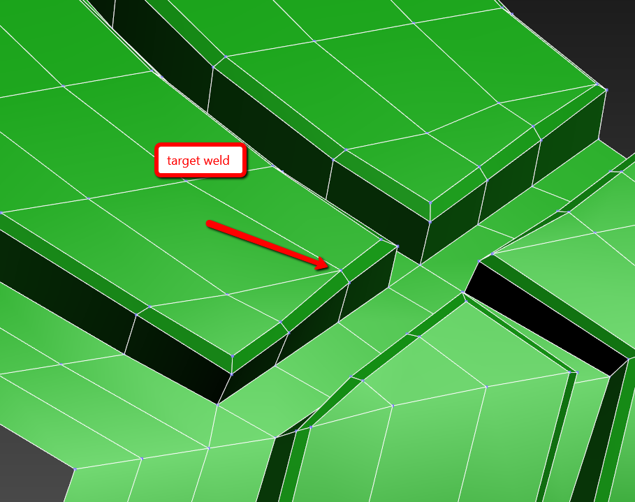
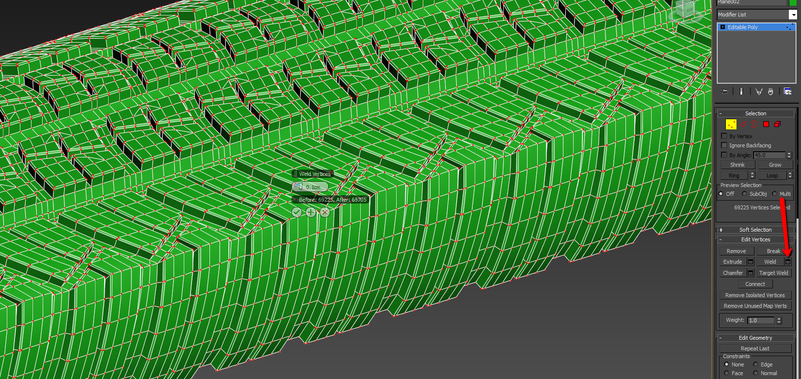
Further choose all points and press weld but don’t make a large sill. You need to connect only the needed points.
Flex our congenerical mesh using bend. As our treads are not straight on the edges we should adapt the angle of tire’s bending to make it cylindrical form using our eyes only.
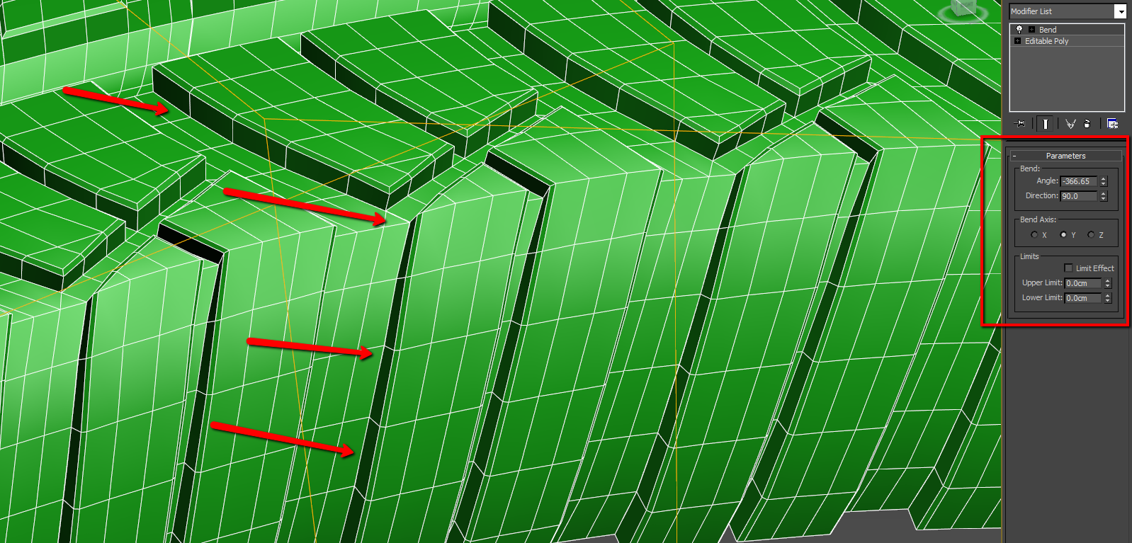
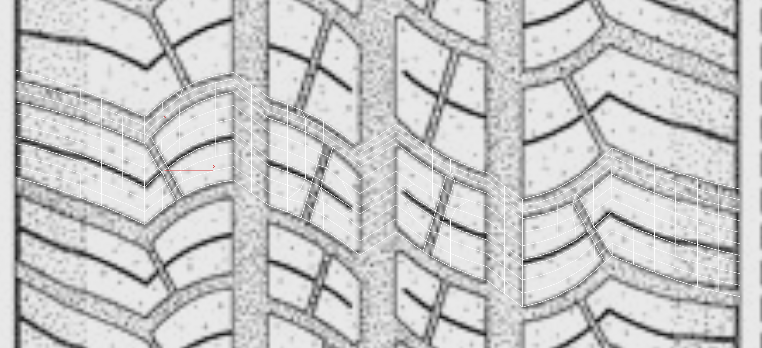
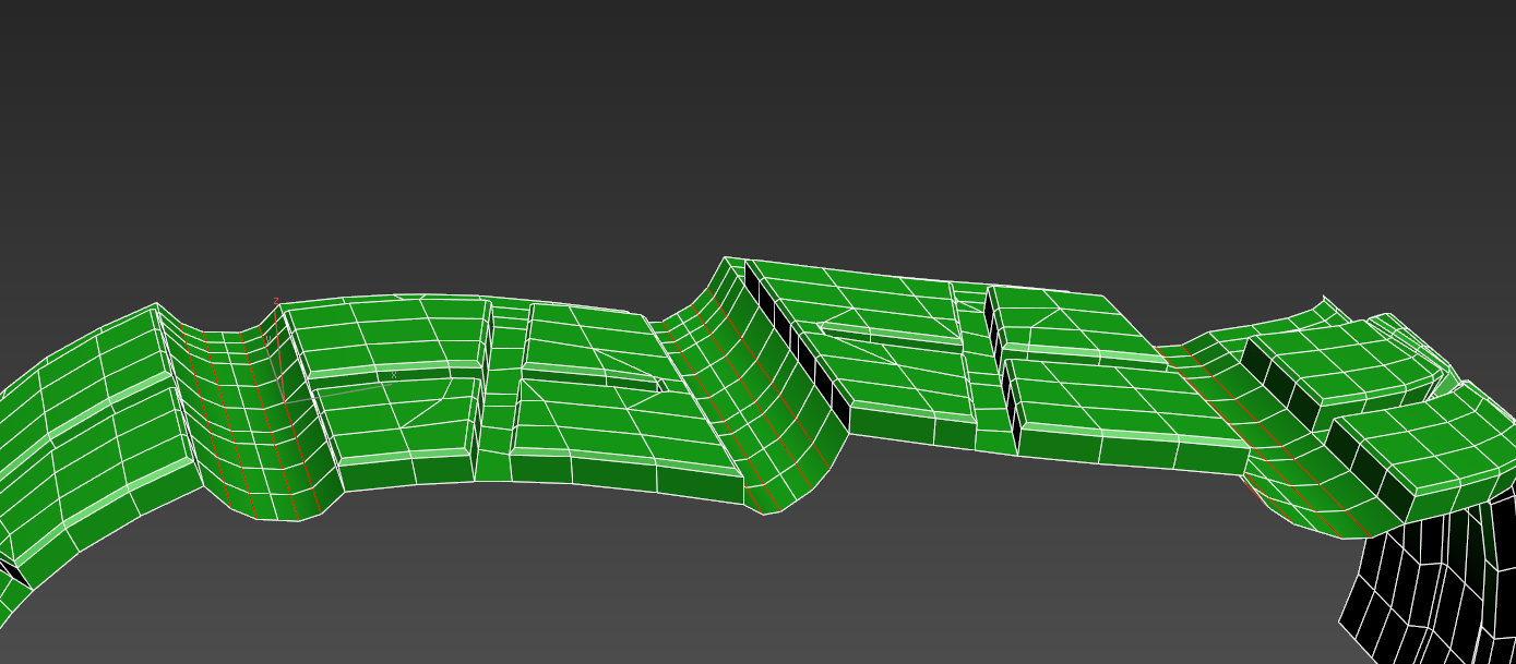
I’ve got the following parameters. Perhaps you will get other ones. As you can see the joint is almost invisible. Let’s convert in editable poly and link with hands using collapse to be sure. We can see that the tire is a little bit narrow and the tread is too close down to the welt.
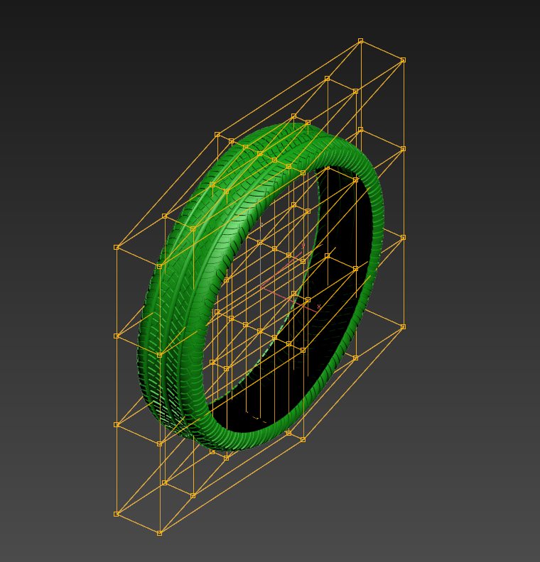
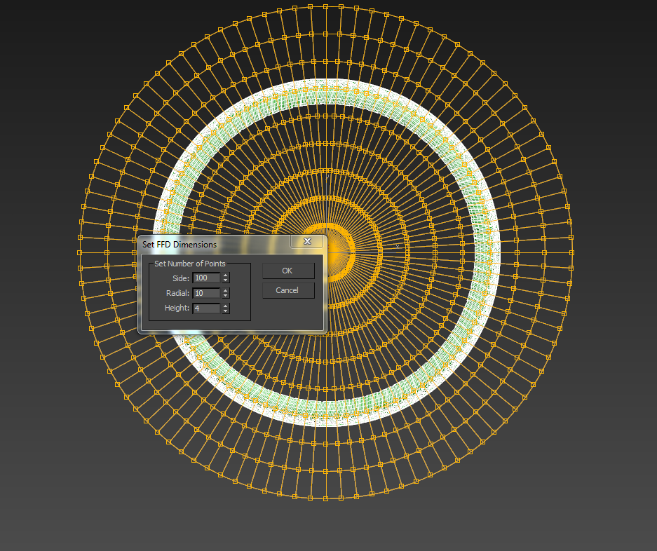
It is needed to adapt the proportions using FDD(cyl). From the previous lesson we remember that it distorts mesh. Accounting that loops around the circle are not similar we should make segments number a little bit more. For example it is 100. But sometimes this modifier doesn’t see in which flatness the radial surface is.
But it is ok. Just delete FFD(cyl) and go to the mode of picking elements. Pick the element and turn it the way that the axis goes up firstly. Don’t forget to include the angular anchor.
Now for your convenience turn the whole object the way to make the tire to stand as on the car. And again FFD(cyl).
Let’s adapt proportions to make it look natural.
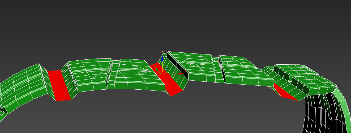
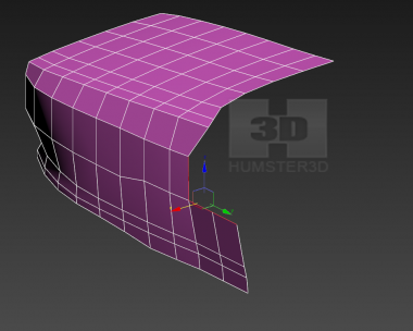
Let’s make the welt. Extrude using click and drag.
As our tire is symmetric – delete the part of the tire where the welt was made.
Now we have to make specification on the welt.
Locate edge ring
Further connect on 2 elements.
Let’s locate polygons between new loops and extrude.
Allocate 4 loops along the formed polygons.
And we make chamfer.
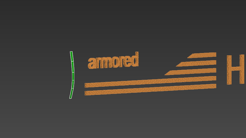
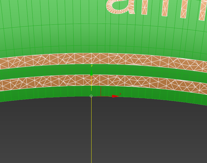
Now we have to make some decals. Without them the tire looks empty. So we choose border on the inner tire’s rim.
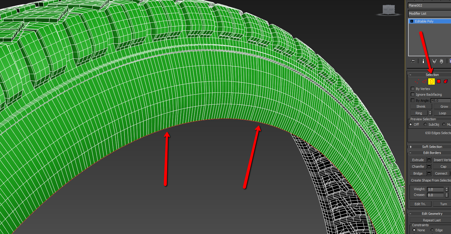
And we create shape using these ribs
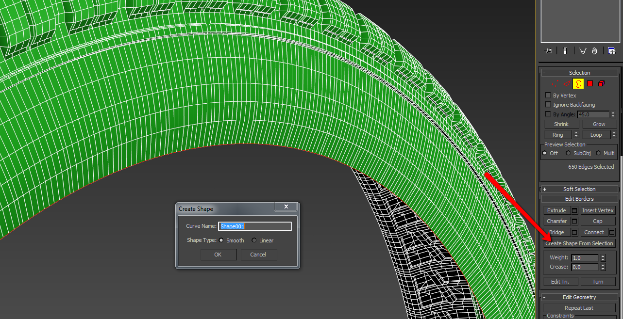
Further we choose ribs around the radius and do the same
It is required to make decals that will take their place. Measure the length.
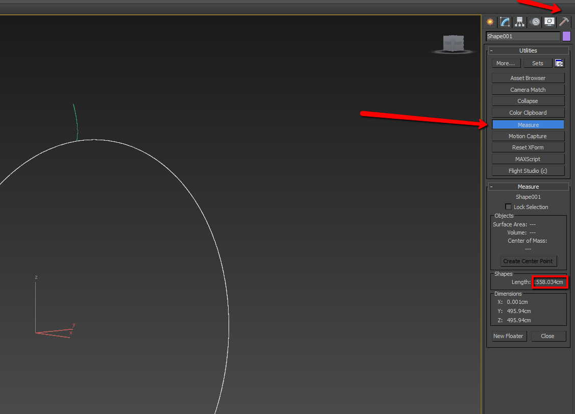
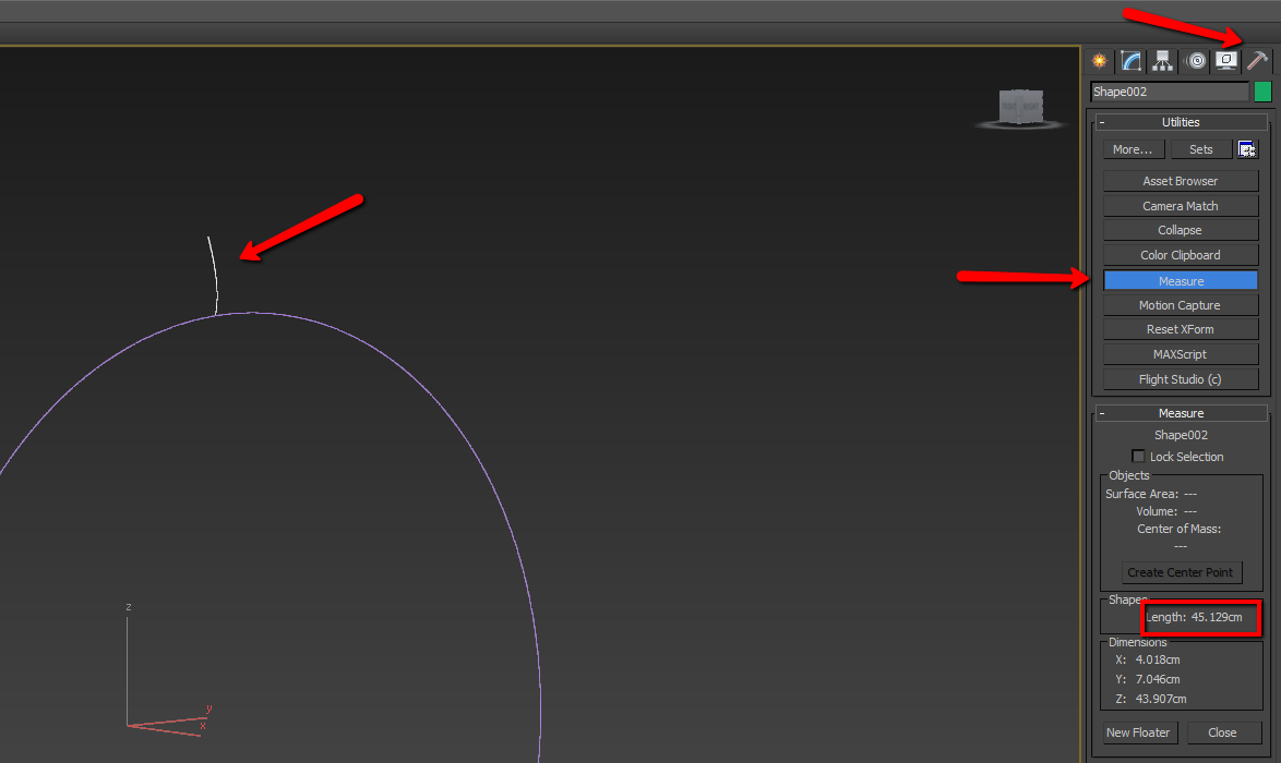
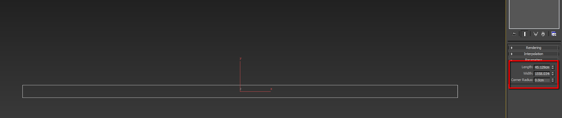
Now we create Rectangle with the following proportions. These are the borders of our decals.
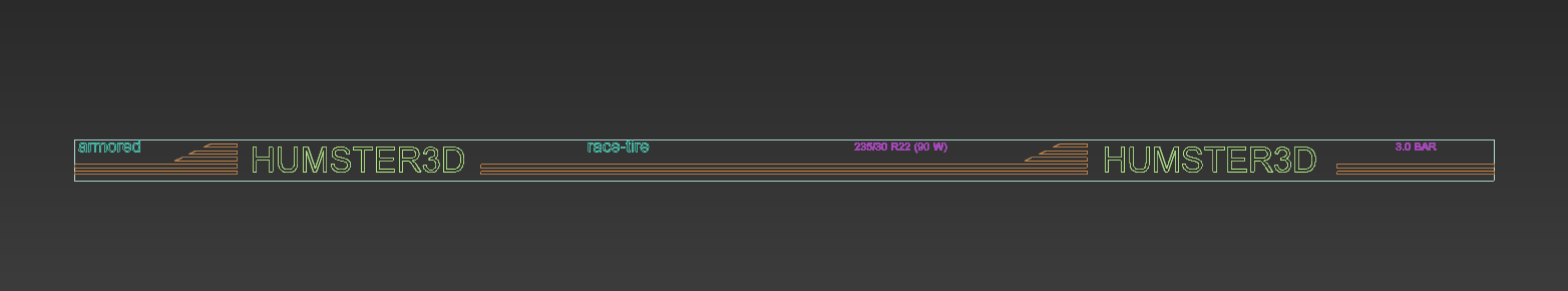
I create various decals which help to make the welt to look interesting I think. If you have specific reference than you should work according to this reference.
Delete Rectangle and join it into one spline.

Than convert this shape into editable poly. The polygon creates in closed spline, if it is not created in your case – then your spline is not closed.
Now we allocate using Ctrl+A all border and click&drag to short distance.
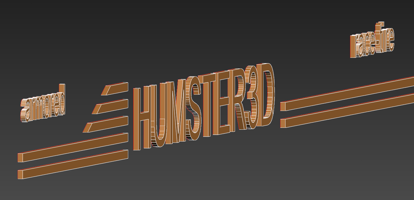
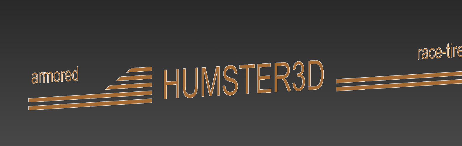
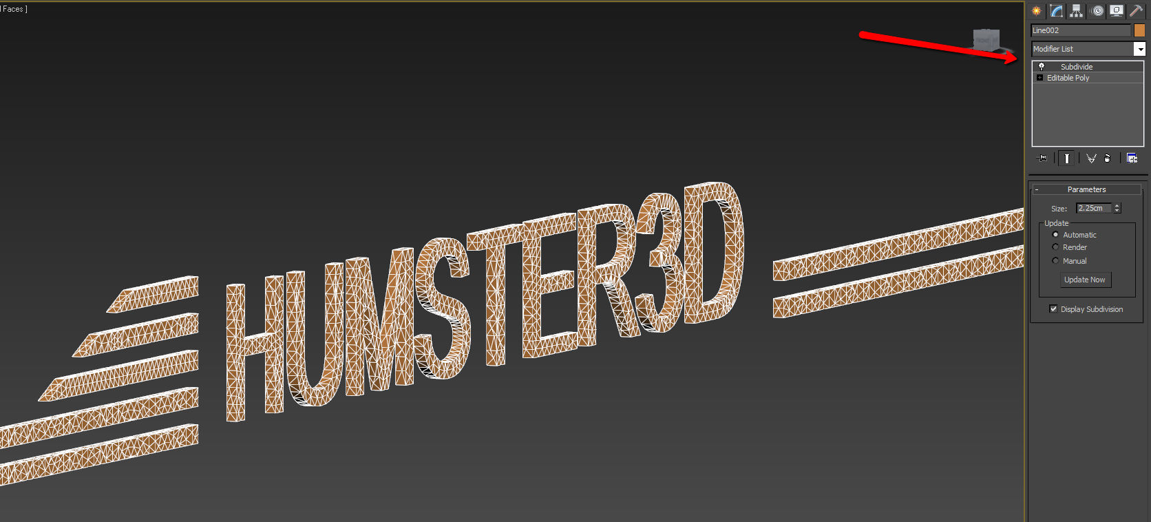
Use modifier subdivide to get topology that will flex in a normal way.
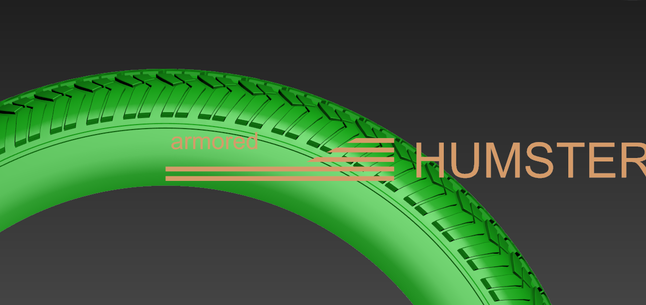
Now we set our decals in a way that their beginning will stand strictly in the center of a tier being at the level that it should stand in the result.
Make detach as clone of welt’s segment that is vertical to the maximum. According to this segment we will adapt our decals using FFD.
We should delete the polygons on the decals’ edges that should create uninterrupted surface.
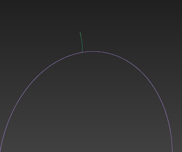
Now the most important part goes. We need to make the same curve as it is on the main part of a tier. So we move pivot of the decals in the same point of pivot of a tier.
And we use modifier bend
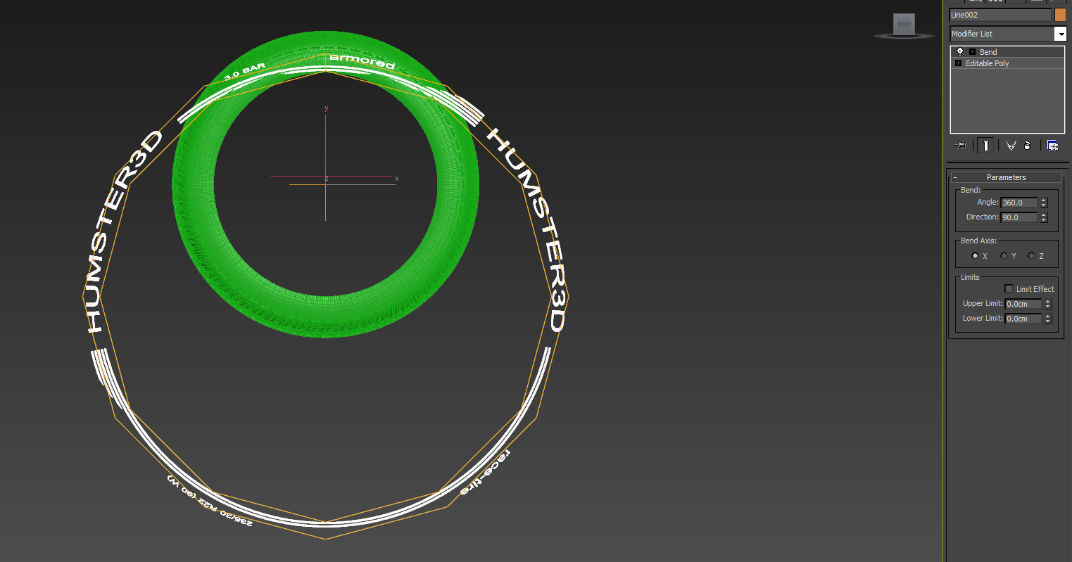
Then we switch to gizmo control mode.
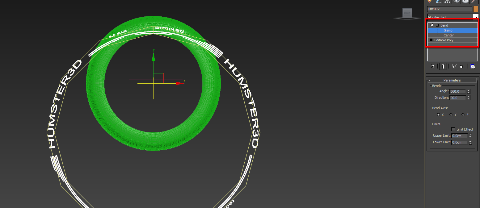
And with included anchor we put it in this point

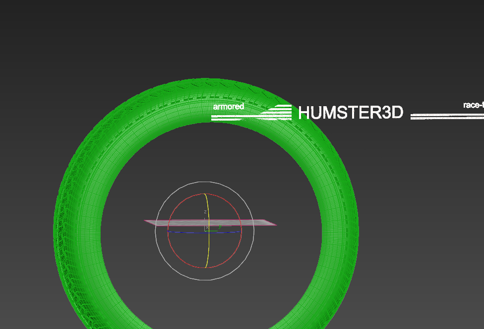
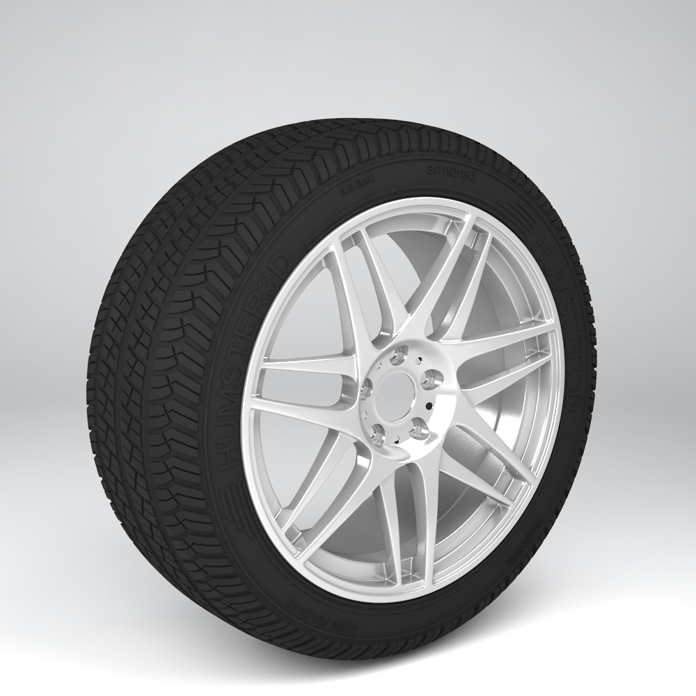
As we can see the title really took its place. Let’s join all parts into one object.
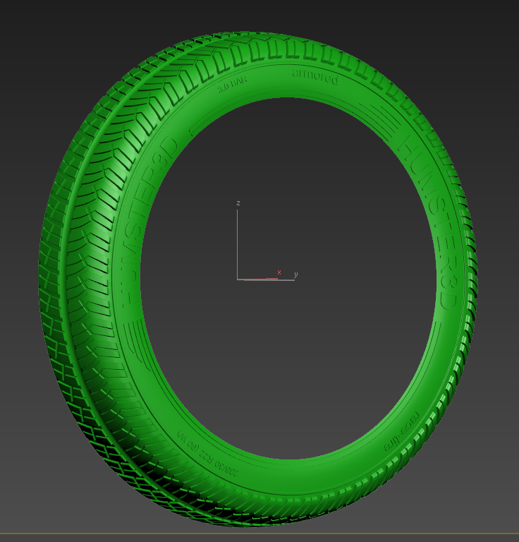
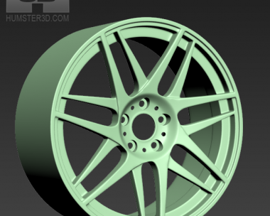
We double our tier in relation to the center to make its second part. At once we should use gray material to evaluate the work that has been done easily.
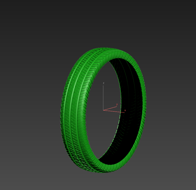
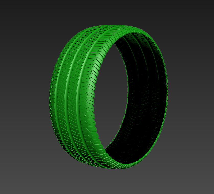
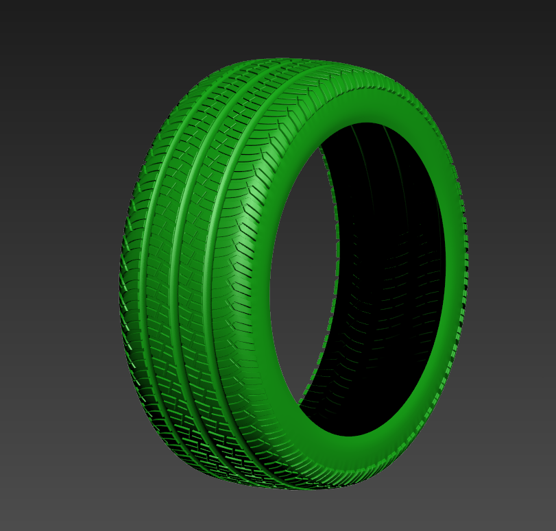
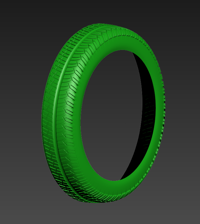
The tire is ready. Now if you want you may join it with the drive that we made last time and make render.
This is our result.
I hope you like your results as well.
Have a nice render!


Add a comment